Isuzu D-Max / Isuzu Rodeo (TFR/TFS). Manual — part 615
EXHAUST GAS RECIRCULATION (EGR) SYSTEM 6E– 5
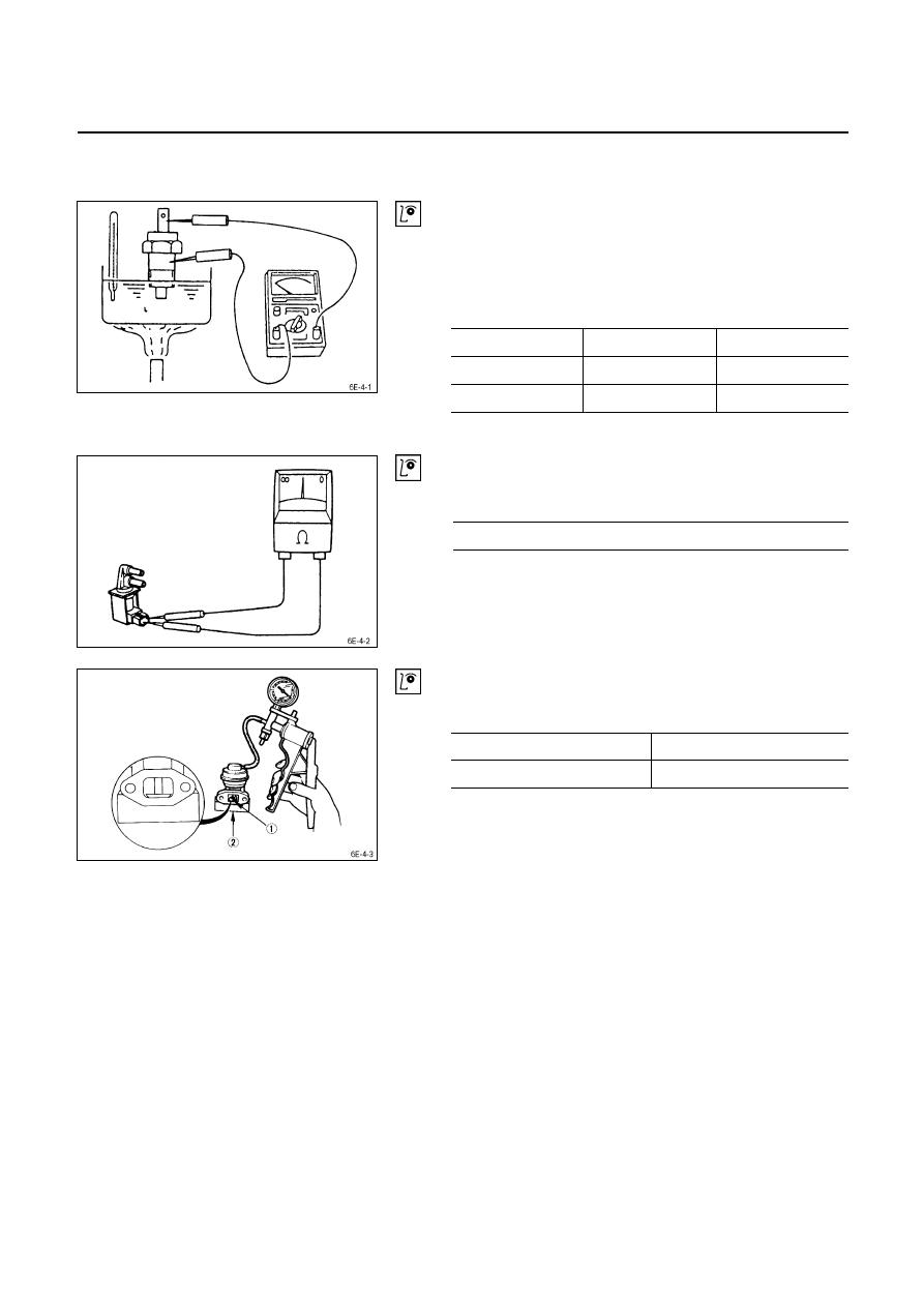
INSPECTION
Thermo Switch
1. Submerge end of switch in water.
2. Connect circuit tester to the connector terminals.
3. Use a burner to heat the water.
4. Check the continuity test across.
Operating temperature
Thermo sw. No.2 Thermo sw. No.1
OFF
→ ON
Over 73°C
Over 30°C
ON
→ OFF
76°C ~ 84°C
36°C ~ 44°C
If there is no continuity, replace the switch.
Vacuum switch valve (VSV)
Use a circuit tester to measure the V.S.V. resistance.
V.S.V Resistance
Ω at 20°C
35 ~ 45
If the resistance is not within specification, replace it.
EGR Valve
Apply Vacuum to the EGR Valve, check to see the Valve
Apply Vacuum
Less then 120 mmHg
Not operation
More than 180 mmHg
Operation
6E – 6 EXHAUST GAS RECIRCULATION (EGR) SYSTEM
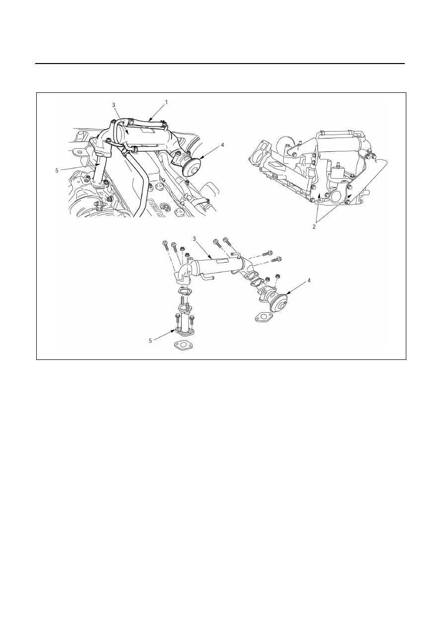
EGR COOLER (For 4JA1TC Engine)
Removal Steps
Installation Steps
Preparation:
・ Disconnect battery ground cable
To install, follow the removal procedure in
reverse order.
・ Drain coolant
J
5.
EGR pipe
・ Remove the intercooler
J
4.
EGR valve
1.
Water hose
J
3.
EGR cooler ASM
2.
EGR cooler bracket
J
2.
EGR cooler bracket
3.
EGR cooler ASM
J
1.
Water hose
4.
EGR valve
5.
EGR pipe
057L200024

EXHAUST GAS RECIRCULATION (EGR) SYSTEM 6E– 7
Installation Steps
5. EGR
Pipe
Install the EGR pipe to the Exhaust manifold and tighten
the EGR pipe bolt with EGR pipe gasket to the specified
torque.
EGR Pipe Bolt Torque
kg·m (lb·ft/N·m)
2.4
± 0.5 (17.4 ± 3.6/23.5 ± 5)
4. EGR
Valve
Install the EGR valve to the intake manifold and tighten the
EGR valve nut with EGR valve gasket to the specified
torque.
EGR Valve Nut Torque
kg·m (lb·ft/N·m)
2.4
± 0.5 (17.4 ± 3.6/23.5 ± 5)
3. EGR Cooler ASM
Temporarily install the EGR cooler assembly.
2. EGR Cooler Bracket
1) Temporarily install the EGR cooler bracket Hand-
tighten each of the bolts.
2) Fintal tighten the bolts in the order shown in the
illustration (
QRST)
.
QR
Torque kg·m
(lb·ft/N·m)
2.4
± 0.5 (17.4 ± 3.6/23.5 ± 5)
ST
Torque kg·m
(lb·ft/N·m)
1.9
± 0.5 (14 ± 3.6/19 ± 5)
1. Water
Hose
Connect the water hose to the EGR cooler ASM.
Note:
•
Take care not to scratch the installation surfaces.
•
Do not allow dirt to adhere to the installation
surfaces.
057L200022
057L200021
057L200023
EXHAUST SYSTEM 6F – 1
SECTION 6F
EXHAUST SYSTEM
TABLE OF CONTENTS
PAGE
General Description. . . . . . . . . . . . . . . . . . . . . . . . . . ... 6F - 2
Removal and Installation. . . . . . . . . . . . . . . . . . . . . . . . ... 6F - 6
Inspection and Repair . . . . . . . . . . . . . . . . . . . . . . . . . ... 6F -11
Turbocharger . . . . . . . . . . . . . . . . . . . . . . . . . . . . . . 6F -12
Main Data and Specifications . . . . . . . . . . . . . . . . . . . . . ... 6F -12
General Description. . . . . . . . . . . . . . . . . . . . . . . . . . ... 6F -13
Inspection and Repair . . . . . . . . . . . . . . . . . . . . . . . . . ... 6F -15
Special Tools. . . . . . . . . . . . . . . . . . . . . . . . . . . . . .. 6F -17
IHI Service Network . . . . . . . . . . . . . . . . . . . . . . . . . . ... 6F -18
INDEX
Нет комментариевНе стесняйтесь поделиться с нами вашим ценным мнением.
Текст