Isuzu D-Max / Isuzu Rodeo (TFR/TFS). Manual — part 1135
ELECTRICAL-BODY AND CHASSIS 8-297
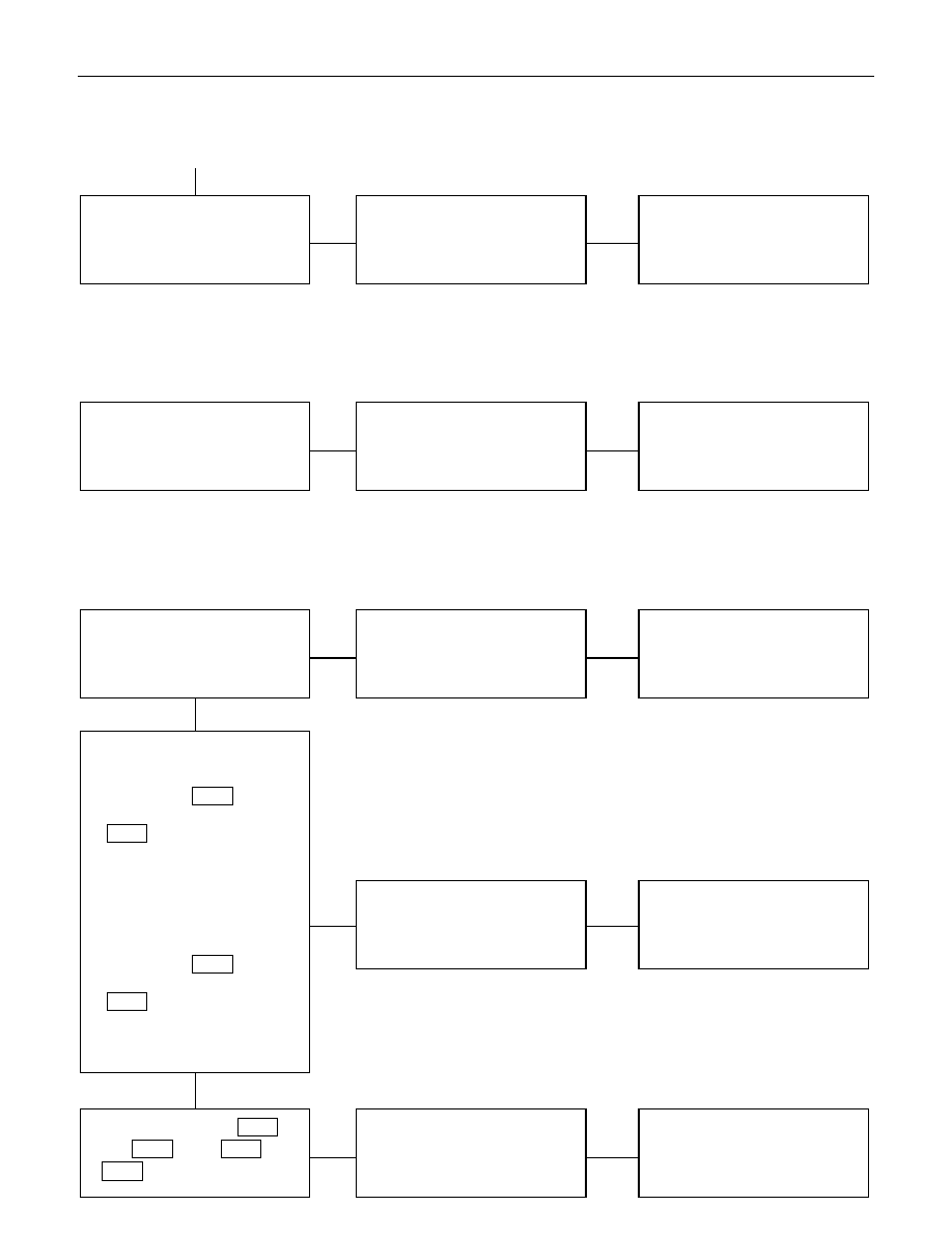
CheckpointTrouble Cause
Count
ermeasure
Replace the driver seat side
power window & door lock
SW.
SW. malfunction
OK
NG
Driver seat side power window
& door lock SW. function
Continued from the previous page
2. Lock switch does not function
CheckpointTrouble Cause
Count
ermeasure
Replace the driver seat side
power window & door lock
SW.
SW. malfunction
NG
Driver seat side power window
& door lock SW. function
3. Window on the driver’s side does not operate
CheckpointTrouble Cause
Count
ermeasure
Replace the driver seat side
power window & door lock
SW.
SW. malfunction
NG
Replace the driver seat side
power window motor
Motor malfunction
NG
OK
Driver seat side power window
& door lock SW. function
OK
Repair open circuit or
connector contact
Open circuit or poor connector
contact
NG
Continuity between 1
D-5
and 2
D-1
, or 10
D-5
and
1
D-1
1. Driver seat side power
window motor function
when connection the motor
connector 2
D-1
to the
battery (+) terminal, and 1
D-1
to the (-) terminal
(Should the motor rotate in
the “UP” direction of the
window)
2. Driver seat side power
window motor function
when connecting the motor
connector 1
D-1
to the
battery (+) terminal, and 2
D-1
to the (-) terminal
(Should the motor rotate in
the “DOWN” direction of the
window)
8-298 ELECTRICAL-BODY AND CHASSIS
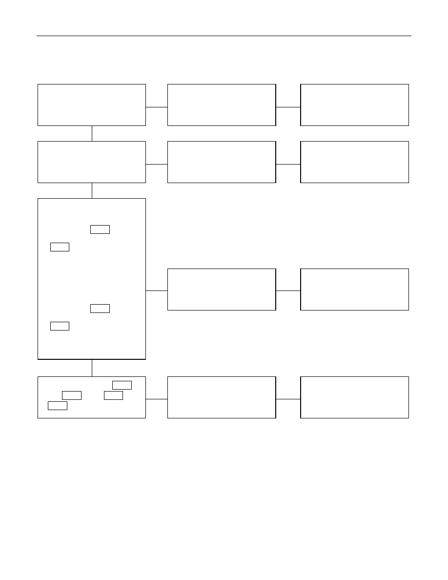
4. Window on the front passenger’s side does not operate
CheckpointTrouble Cause
Count
ermeasure
Replace the front passenger’s
power window & door lock
SW.
SW. malfunction
NG
Replace the front passenger’s
power window motor
Motor malfunction
NG
OK
Driver seat side power window
& door lock SW. function
OK
Repair open circuit or
connector contact
Open circuit or poor connector
contact
NG
Continuity Between 6
D-10
and 2
D-6
, or 10
D-10
and
1
D-6
1. Front passenger’s power
window motor function
when connecting the motor
connector 2
D-6
to the
battery (+) terminal, and 1
D-6
to the (-) terminal
(Should the motor rotate in
the “UP” direction of the
window)
2. Front passenger’s power
window motor function
when connecting the motor
connector 1
D-6
to the
battery (+) terminal, and 2
D-6
to the (-) terminal.
(Should the motor rotate in
the “DOWN” direction of the
window)
Replace the driver seat side
power window & door lock
SW.
SW. malfunction
NG
OK
Front passenger’s window &
door lock SW. function

ELECTRICAL-BODY AND CHASSIS 8-299
5. Rear window on the left (right) side does not operate
CheckpointTrouble Cause
Count
ermeasure
Replace the driver seat side
power window & door lock
SW.
SW. malfunction
NG
Replace the rear power
window motor
Motor malfunction
NG
OK
Driver seat side power window
& door lock SW. function
OK
Repair open circuit or
connector contact
Open circuit or poor connector
contact
NG
Continuity between 5
D-12
and 2
D-11
(5
D-16
and 2 D-
15), or 6
D-12
and 1
D-11
(6
D-16
and1
D-15
)
1. Rear power window motor-
LH (RH) function when
connecting the motor
connector 2
D-11
(2
D-15
) to the battery (+)
terminal, and 1
D-11
(1
D-15
) to the (-) terminal
(Should the motor rotate in
the “UP” direction of the
window)
2. Rear power window motor-
LH (RH) function when
connecting the motor
connector 1
D-11
(1
D-15
) to the battery (+)
terminal, and 2
D-11
(2
D-15
) to the (-) terminal
(Should the motor rotate in
the “DOWN” direction of the
window)
Replace the rear power
window SW. -LH (RH)
SW. malfunction
NG
OK
Rear power window SW. LH
(RH) function
8-300 ELECTRICAL-BODY AND CHASSIS
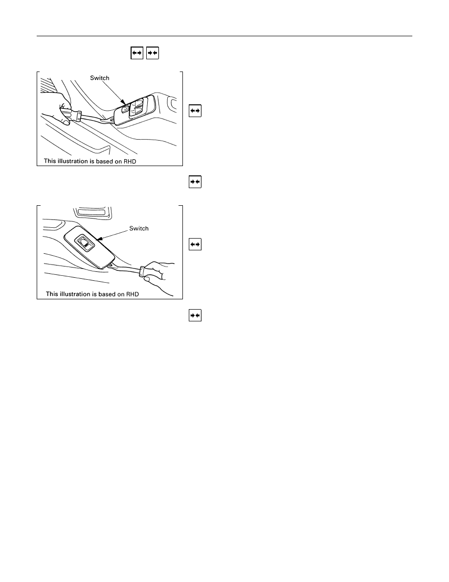
REMOVAL AND INSTALLATION
DRIVER SEAT SIDE POWER WINDOW &
DOOR LOCK SWITCH
(2 DOORS MODEL)
Removal
1. Remove the switch by pushing the spring with the tip of a
screwdriver.
2. Disconnect the connector.
Installation
To install, follow the removal steps in the reverse order.
FRONT PASSENGER’S POWER WINDOW
& DOOR LOCK SWITCH
(2 DOORS MODEL)
Removal
1. Remove the switch by pushing the spring with the tip of a
screwdriver.
2. Disconnect the connector.
Installation
To install, follow the removal steps in the reverse order.
Нет комментариевНе стесняйтесь поделиться с нами вашим ценным мнением.
Текст