Isuzu D-Max / Isuzu Rodeo (TFR/TFS). Manual — part 1407
ELECTRICAL-BODY AND CHASSIS 8-193
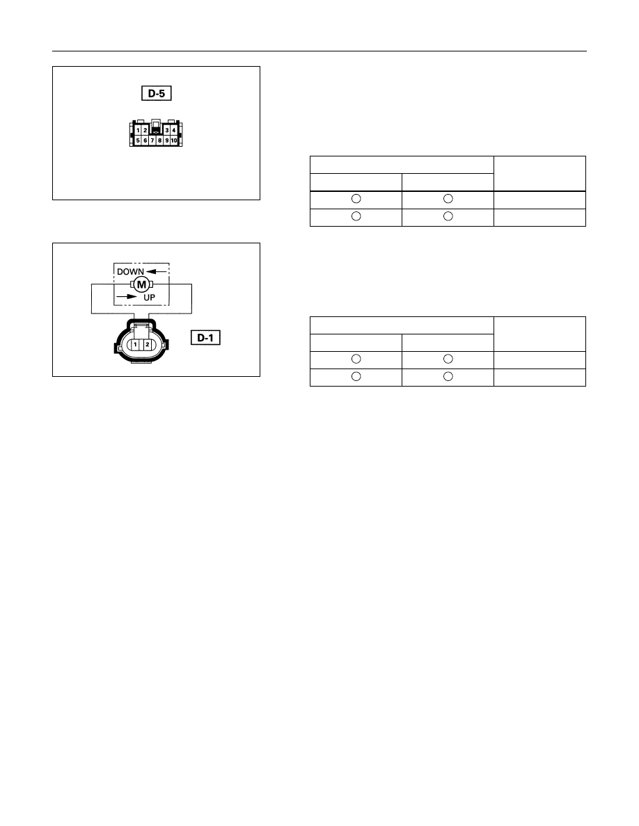
Harness side
Driver Seat Side Power Window Motor
1. Driver Seat Side Power Window & Door Lock Switch
Connector Circuit
Disconnect the switch connector, apply the battery voltage
(12V) to the harness side connector terminals and check
operation.
Connecting terminals
Operation
1 (L/R)
10 (L/W)
direction
-
+
DOWN
+
-
UP
2. Driver Seat Side Power Window Motor Connector
Circuit
Disconnect the switch connector, apply the battery voltage
(12V) to the motor side connector terminals and check
operation.
Connecting terminals
Operation
1
2
direction
+
-
DOWN
-
+
UP

8-194 ELECTRICAL-BODY AND CHASSIS
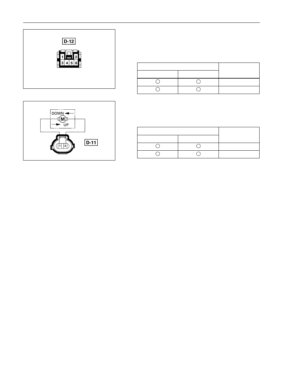
Harness side
Front Passenger’s Power Window Motor
1. Front Passenger’s Power Window Switch & Door Lock
Switch Connector Circuit
Disconnect the motor connector, apply the battery voltage
(12V) to the harness side connector terminals and check
operation.
Connecting terminals
Operation
6 (L/R)
10 (L/W)
direction
-
+
DOWN
+
-
UP
2. Front Passenger’s Power Window Motor Connector
Circuit
Disconnect the switch connector, apply the battery voltage
(12V) to the motor side connector terminals and check
operation.
Connecting terminals
Operation
1
2
direction
+
-
DOWN
-
+
UP
ELECTRICAL-BODY AND CHASSIS 8-195
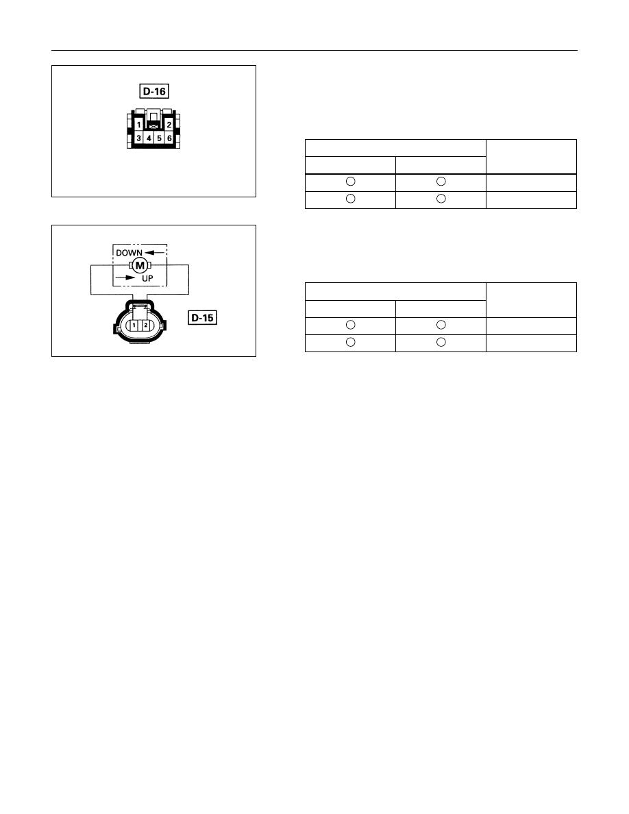
Harness side
Rear Passenger’s Power Window Motor-LH
1. Rear Power Window Switch-LH Connector Circuit
Disconnect the motor connector, apply the battery voltage
(12V) to the harness side connector terminals and check
operation.
Connecting terminals
Operation
5 (L/R)
6 (BR/W)
direction
-
+
DOWN
+
-
UP
2. Rear Power Window Motor-LH Connector Circuit
Disconnect the switch connector, apply the battery voltage
(12V) to the motor side connector terminals and check
operation.
Connecting terminals
Operation
1
2
direction
+
-
DOWN
-
+
UP
8-196 ELECTRICAL-BODY AND CHASSIS
Harness side
Rear Power Window Motor-RH
1. Rear Power Window Switch-RH Connector Circuit
Disconnect the motor connector, apply the battery voltage
(12V) to the harness side connector terminals and check
operation.
Connecting terminals
Operation
5 (L/R)
6 (BR/W)
direction
-
+
DOWN
+
-
UP
2. Rear Power Window Motor-RH Connector Circuit
Disconnect the switch connector, apply the battery voltage
(12V) to the motor side connector terminals and check
operation.
Connecting terminals
Operation
1
2
direction
+
-
DOWN
-
+
UP
Нет комментариевНе стесняйтесь поделиться с нами вашим ценным мнением.
Текст