Isuzu D-Max / Isuzu Rodeo (TFR/TFS). Manual — part 2042
3B-58 STEERING
Important Operations
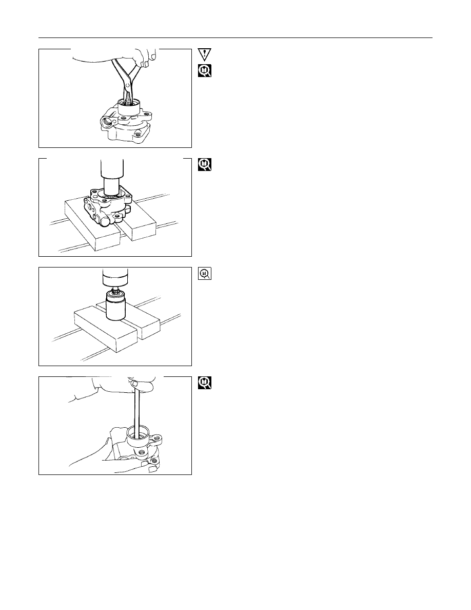
11.Snap Ring
Use a pair of snap ring pliers to remove the snap ring.
12.Shaft
Use a bench press to slowly force the shaft from the rear cover
side.
Note :
Take care not to damage the end of the shaft when
removing the shaft.
13.Bearing
Use the bench press and bearing remover.
Bearing Remover : 5-8840-2206-0
Note :
Take care not to damage the shaft when removing the
shaft.
16.Oil Seal
Use a suitable bar.
STEERING 3B-59
INSPECTION AND REPAIR (C22, C20 Series Engine Model)
Make all necessary adjustments, repairs, and part replacements if wear, damage, or other problems are discovered
during inspection.
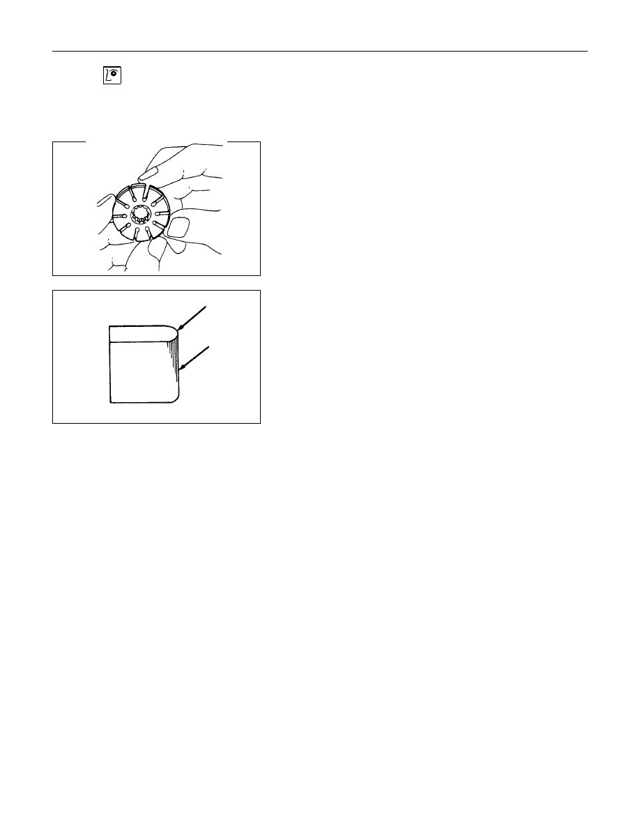
Rotor
Check that the groove in the vane is free from excessive wear
and that the vane slides smoothly.
When part replacement becomes necessary, the pump
cartridge should preferably be replaced as a sub assembly.
Vane
Sliding faces of the vane should be free from wear.
(particularly the curved face at the tip in contact with the cam
should be free from wear and distortion.)
When part replacement becomes necessary, the pump
cartridge should preferably be replaced as a sub assembly.
Cam
The inner face of the cam should have a trace of uniform
contact without a sign of step wear.
When part replacement becomes necessary, the pump
cartridge should preferably be replaced as a sub assembly.
Pressure Plate and Thrust Plate
The sliding faces of the parts must be free from step wear
(more than 0.01 mm) which can be felt by the finger nail.
The parts with minor scores may be reused after lapping the
face.
Shaft
Oil seal sliding faces must be free from a step wear which can
be felt by the finger nail.
3B-60 STEERING
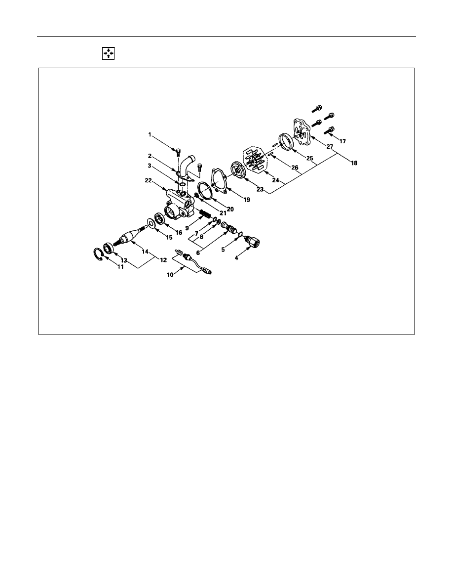
REASSEMBLY (C22, C20 Series Engine Model)
Reassembly Steps
1. Rear housing
2. Pin
3. Cam
4. Rotor and vane
V
5. Pressure plate
6. Front housing
7. O-ring
8. O-ring
9. Gasket
10. Rear housing assembly and pump
cartridge
V
11. Bolt
V
12. Oil seal
13. Retaining ring
14. Shaft
15. Bearing
V
16. Shaft assembly
V
17. Retaining ring
18. Pressure switch
19. Spring
20. Filter
21. Retaining ring
22. Valve
23. O-ring
V
24. Connector
25. O-ring
26. Pipe, suction
27. Bolt
STEERING 3B-61
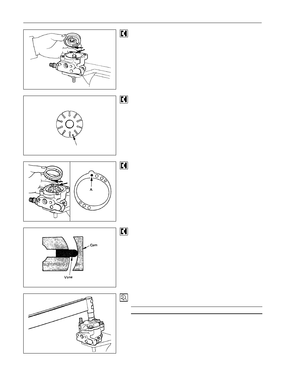
5. Pressure Plate
When installing the pressure plate, align the projection of
pressure plate with the grove of oil pump body.
Rotor
Place the rotor so that specified mark
Q
turns down.
Note :
When part replacement becomes necessary, the pump
cartridge should be replaced as a sub assembly.
Cam
When installing the cam, align the projection of cam with the
grove of oil pump body.
Install the cam with the pin "A" side turn down.
Vane
The round end of the vane should be matched to the inner
surface of the cam ring.
11.Cover and Bolt
Torque
N
⋅
m (kgf
⋅
m/lb
⋅
ft)
53.9
±
4.9 (5.5
±
0.5 / 39.8
±
3.6)
Нет комментариевНе стесняйтесь поделиться с нами вашим ценным мнением.
Текст