Isuzu D-Max / Isuzu Rodeo (TFR/TFS). Manual — part 797
6A–68
ENGINE MECHANICAL (6VD1 3.2L)
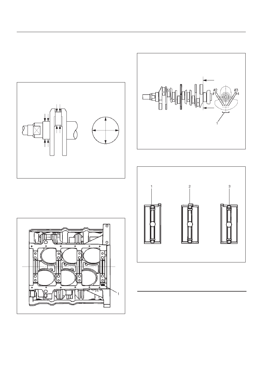
2. Measure the diameter and the uneven wear of main
journal and crank pin. If the crankshaft wear exceeds
the specified limit, crankshaft must be replaced.
Main journal diameter : 63.918 mm–63.933 mm
(2.5165 in–2.5170 in)
Crank pin diameter : 53.922 mm–53.937 mm
(2.1229 in.–2.1235 in.)
Uneven wear limit : 0.005 mm (0.0002 in)
015RS009
Crankshaft Bearing Selection
When installing new crankshaft bearings or replacing
bearings, refer to the selection table below. Select and
install the new crankshaft bearings, paying close
attention to the cylinder block journal hole.
1. Diameter size mark (1) and the crankshaft journal.
015RS010
2. Diameter size mark (1).
The diameter size marks are stamped on the No.1
crankshaft balancer as shown in the illustration.
015RS011
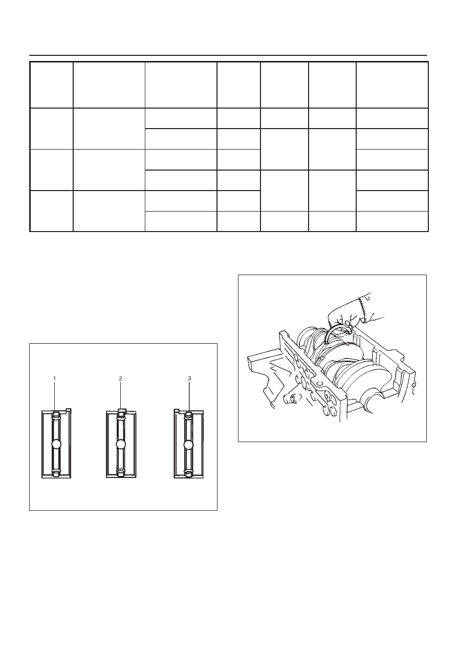
NOTE: Take care to ensure the bearings are positioned
correctly.
015RS012
Legend
(1) Number 1 and 4 main bearing upper and lower
(2) Number 2 and 3 main bearing upper
(3) Number 2 and 3 main bearing lower
6A–69
ENGINE MECHANICAL (6VD1 3.2L)
1 Size
Mark
Main Bearing
Bore Diameter
Crank Shaft Main
Journal Diameter
2 Size
Mark
Crank Shaft
Bearing
Size Mark
(Upper
Side)
Crank Shaft
Bearing
Size Mark
(Lower
Side)
Oil Clearance
(Reference)
1
68.994-69.000
63.918-63.925
(2.5165-2.5167)
2
Blue
Blue
0.030-0.049
(0.0012-0.0019)
1
(2.7163-2.7165)
63.926-63.933
(2.5168-2.5170)
1
Brown
Brown
0.028-0.047
(0.0011-0.0019)
2
68.987-68.993
63.918-63.925
(2.5165-2.5167)
2
Brown
Brown
0.029-0.048
(0.0011-0.0019)
2
(2.7160-2.7163)
63.926-63.933
(2.5168-2.5170)
1
Green
Green
0.027-0.046
(0.0011-0.0018)
3
68.980-68.986
63.918-63.925
(2.5165-2.5167)
2
Green
Green
0.028-0.047
(0.0011-0.0019)
3
(2.7157-2.7160)
63.926-63.933
(2.5168-2.5170)
1
Yellow
Yellow
0.026-0.045
(0.0010-0.0018)
Reassembly
1. Crankshaft (12)
D
Install the main bearings to the cylinder block and
the main bearing caps.
D
Be sure that they are positioned correctly.
D
Apply new engine oil to the upper and lower main
bearing faces.
NOTE: Do not apply engine oil to the main bearing back
faces.
015RS012
D
Carefully mount the crankshaft.
D
Apply engine oil to the thrust washer.
D
Assemble the thrust washer to the No.3 bearing
journal. The oil grooves must face the crankshaft.
015RS013
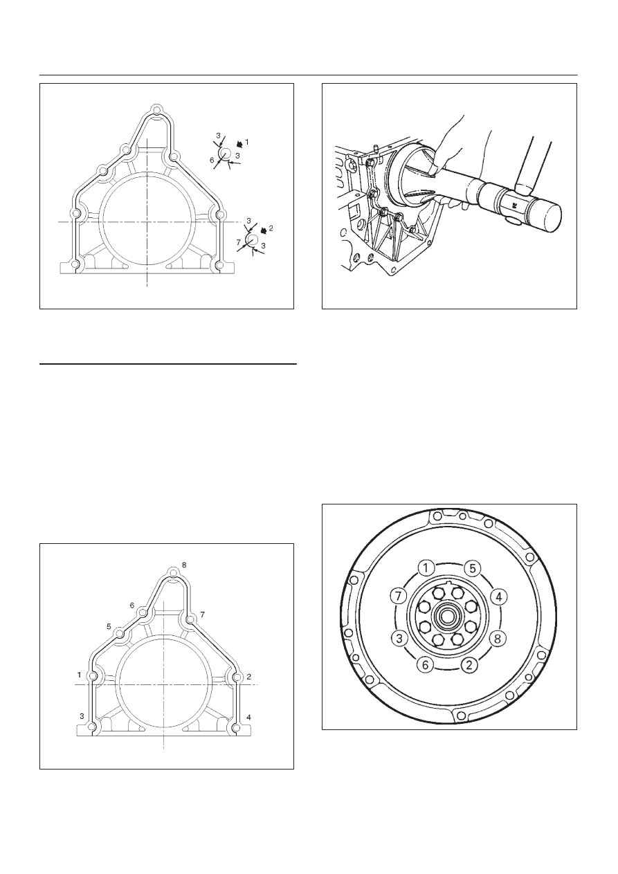
2. Rear oil seal (10)
D
Remove the oil from the cylinder block and the
retainer mounting surface.
D
Apply sealant (TB–1207B or equivalent) to the
retainer mounting surface, following the pattern
shown in the illustration.
The retainer must be installed within 5 minutes after
sealant application befor the sealant hardens.
6A–70
ENGINE MECHANICAL (6VD1 3.2L)
015RW002
Legend
(1) Around Bolt Holes
(2) Around Dowel Pin
D
Apply engine oil to the oil seal lip.
D
Align the cylinder block dowel pin holes with the rear
retainer dowel pins.
D
Tighten the rear retainer fixing bolts. New bolts
should be used when installing rear retainer.
Torque: 18 N·m (1.8 Kg·m/13 lb ft)
NOTE: Be very careful not to disengage the oil seal garter
spring during installation of the rear retainer.
If the seal was removed from retainer for
replacement, apply engine oil to the oil seal lip and
install the oil seal using 5–8840–2286–0 oil seal
installer.
015RW001
015RS017
3. Flywheel (9)
1. Thoroughly clean and remove the oil from the
threads of crankshaft.
2. Remove the oil from the crankshaft and flywheel
mounting faces.
3. Mount the flywheel on the crankshaft and then
install the washer.
4. Hold the crankshaft to prevent from rotating then
install the bolts in the order shown to the specified
torque.
Torque: 54 N·m (5.5 Kg·m/40 lb ft)
NOTE: Do not reuse the bolt and do not apply oil or thread
lock to the bolt.
015RS018
6A–71
ENGINE MECHANICAL (6VD1 3.2L)
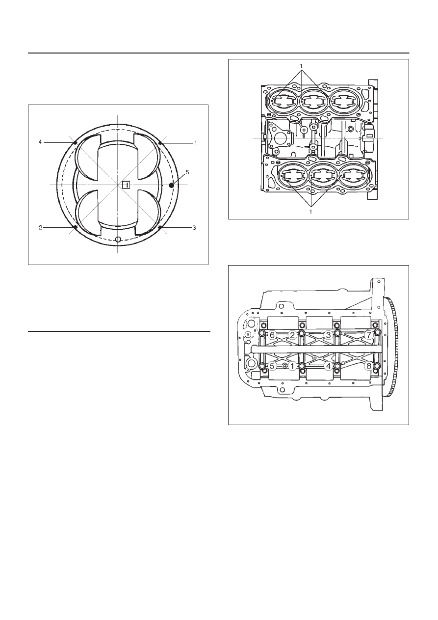
4. Piston and connecting rod assembly (8)
D
Apply engine oil to the cylinder bores, the
connecting rod bearings and the crankshaft pins.
Check to see that the piston ring end gaps are
correctly positioned.
015RS019
Legend
(1) No.1 Compression Ring
(2) No.2 Compression Ring
(3) Oil Ring Side Rail Upper
(4) Oil Ring Side Rail Lower
(5) Piston Front Mark
D
Insert the piston/connecting rod assemblies into
each cylinder with the piston ring compressor. The
front marks must be facing the front of the engine.
D
Match the numbered caps with the numbers on the
connecting rods. Align the punched marks on the
connecting rods and caps.
D
Apply engine oil to the threads and seating faces of
the nuts.
D
Tighten the nuts.
Torque: 54 N·m (5.5 Kg·m/40 lb ft)
After tightening the cap nuts, check to see that the
crankshaft rotates smoothly.
NOTE: Do not apply engine oil to the bearing back faces.
015RS020
5. Install oil gallery (7) and tighten the bolts in 2 steps, in
the order shown.
1st step: 29 N·m (3.0 Kg·m/22 lb ft)
2nd step: 55
°
∼
65
°
051RS009
6. Cylinder block side bolts (6)
D
Tighten all the bolts to the specified torque in the
order shown.
NOTE: Do not apply engine oil to the crank case side
bolts.
Torque: 39 N·m (4.0 Kg·m/29 lb ft)
Нет комментариевНе стесняйтесь поделиться с нами вашим ценным мнением.
Текст