Isuzu D-Max / Isuzu Rodeo (TFR/TFS). Manual — part 560
6A – 78 ENGINE MECHANICAL
7. After grinding, make sure that the hot plug surfaces
are completely free of protuberances.
The hot plug surfaces must also be free of
depressions.
Once again, lightly tap the hot plug heads to make
sure that they are firmly seated.
Heat Shield Replacement
Heat Shield Removal
After removing the hot plugs, use a hammer
Q
and a
brass bar
R
to lightly tap the lower side of the heat shield
S
and drive it free.
Heat Shield Installation
Install the heat shield to the cylinder head from the nozzle
holder installation hole side. Lightly tap the heat shield
flange into place with a hammer and a brass bar.
The heat shield flange side must be facing up.
Note:
Always install a new heat shield. Never reuse the old
heat shield.
VALVE GUIDE
Valve Stem and Valve Guide Clearance
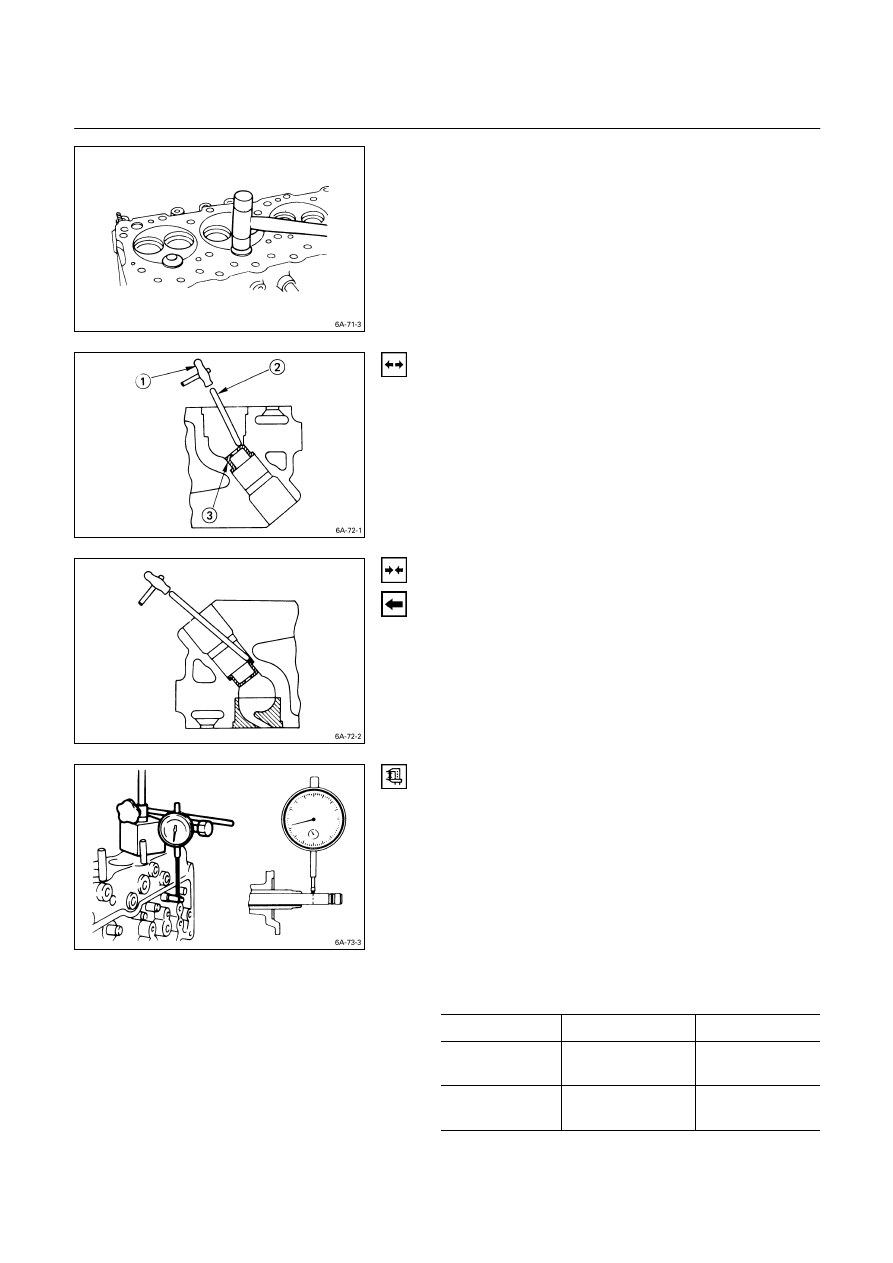
Measuring Method-I
1. With the valve stem inserted in the valve guide, set
the dial indicator needle to “0”.
2. Move the valve head from side to side.
Read the dial indicator.
Note the highest dial indication.
If the measured values exceed the specified limit, the
valve and the valve guide must be replaced as a set.
Valve Stem Clearance
mm (in)
Standard
Limit
Intake Valve
0.039 – 0.069
(0.0015 – 0.0027)
0.200
(0.008)
Exhaust Valve
0.064 – 0.093
(0.0025 – 0.0037)
0.250
(0.0098)
ENGINE MECHANICAL 6A – 79
Measuring Method-II
1. Measure the valve stem outside diameter.
Refer to the Item “Valve Stem Outside Diameter”.
2. Use a caliper calibrator or a telescoping gauge to
measure the valve guide inside diameter.
Valve Guide Replacement
Valve Guide Removal
Use a hammer and the valve guide replacer to drive out
the valve guide from the cylinder head lower face.
Valve Guide Replacer: 9-8523-1212-0
Valve Guide Installation
1. Apply engine oil to the valve guide outer
circumference.
2. Attach the valve guide installer to the valve guide.
3. Use a hammer to drive the valve guide into position
from the cylinder head upper face.
Valve Guide Replacer: 9-8523-1212-0
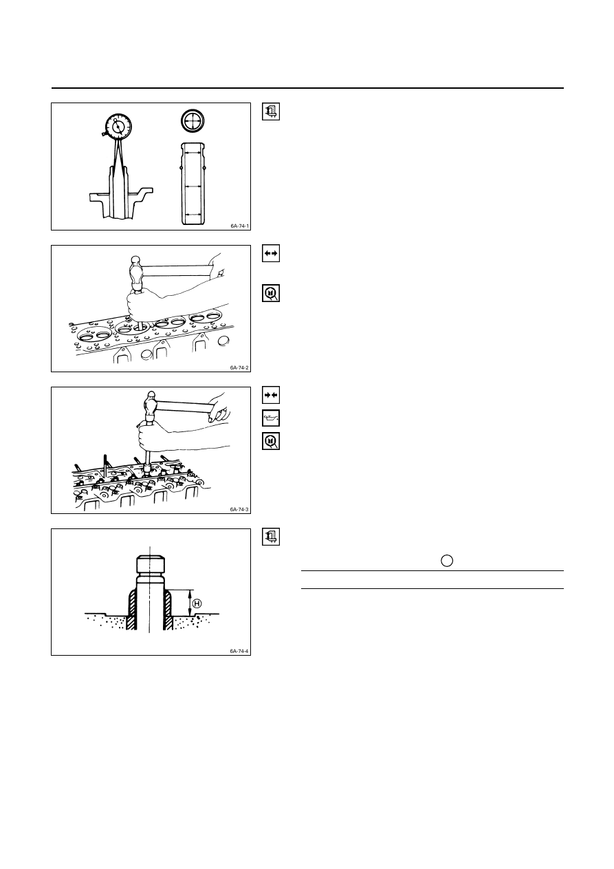
4. Measure the height of the valve guide upper end from
the upper face of the cylinder head.
Valve Guide Upper End Height
H
(Reference) mm (in)
13 (0.51)
Note:
If the valve guide has been removed, both the valve
and the valve guide must be replaced as a set.

6A – 80 ENGINE MECHANICAL
VALVE AND VALVE SEAT INSERT
Valve Stem Outside Diameter
Measure the valve stem diameter at three points.
If the measured value is less than the specified limit, the
valve and the valve guide must be replaced as a set.
Valve Stem Outside Diameter
mm (in)
Standard
Limit
Intake Valve
7.946 – 7.961
(0.3128 – 0.3134)
7.880
(0.3102)
Exhaust Valve
7.921 – 7.936
(0.3119 – 0.3124)
7.850
(0.3090)
Valve Thickness
Measure the valve thickness.
If the measured value is less than the specified limit, the
valve and the valve guide must be replaced as a set.
Intake and Exhaust Valve Thickness
mm (in)
Standard
Limit
4JA1T, 4JA1, 4JB1T,
4JA1TC Engine
1.8 (0.07) 1.5 (0.06)
Inlet 1.34
(0.0528)
4JG2T Engine
Exhaust 1.38 (0.0544)
1.1 (0.043)
Inlet 1.41
(0.0555)
4JH1TC
Exhaust 1.38 (0.0543)
1.1 (0.043)
Valve Depression
1. Install
the
valve
Q
to the cylinder head
R
.
2. Use a depth gauge or a straight edge with steel rule to
measure the valve depression from the cylinder head
lower surface.
If the measured value exceeds the specified limit, the
valve seat insert must be replaced.
Valve Depression
mm (in)
Standard
Limit
Intake 0.73 (0.029) 1.28 (0.050)
4JA1T, 4JA1,
4JB1T, 4JA1TC
Engine
Exhaust 0.70 (0.028) 1.20 (0.047)
4JG2T,
4JH1TC
Engine 1.1 (0.043) 1.6 (0.063)

ENGINE MECHANICAL 6A – 81
3. Check that the rocker arm oil port is free of
obstructions.
If necessary, use compressed air to clean the rocker
arm oil port.
Rocker Arm Correction
Inspect the rocker arm valve stem contact surfaces for
step wear
Q
and scoring
R
.
If the contact surfaces have light step wear or scoring,
they may be honed with an oil stone.
If the step wear or scoring is severe, the rocker arm must
be replaced.
CYLINDER BODY
Cylinder Body Upper Face Warpage
1. Remove the cylinder body dowel.
2. Remove the cylinder liner.
Refer to “Cylinder Liner Replacement”.
3. Use a straight edge
Q
and a feeler gauge
R
to
measure the four sides and the two diagonals of the
cylinder body upper face.
If the measured values exceeds the limit, the cylinder
body must be replaced.
Cylinder Body Upper Face Warpage
mm (in)
Standard
Limit
0.05 (0.002) or less
0.20 (0.008)
Cylinder Body Height
H
(Reference)
mm (in)
Standard
4JA1, 4JA1T,
4JA1TC
244.945 – 245.055 (9.6430 – 9.6478)
4JB1T, 4JG2T,
4JH1TC
269.945 – 270.055 (10.6277 – 10.6320)
5. Reinstall the cylinder liner.
Refer to “Cylinder Liner Replacement”.
6. Reinstall the cylinder body dowel.
Нет комментариевНе стесняйтесь поделиться с нами вашим ценным мнением.
Текст