Isuzu D-Max / Isuzu Rodeo (TFR/TFS). Manual — part 1843
7A1-34 CONSTRUCTION AND FUNCTION
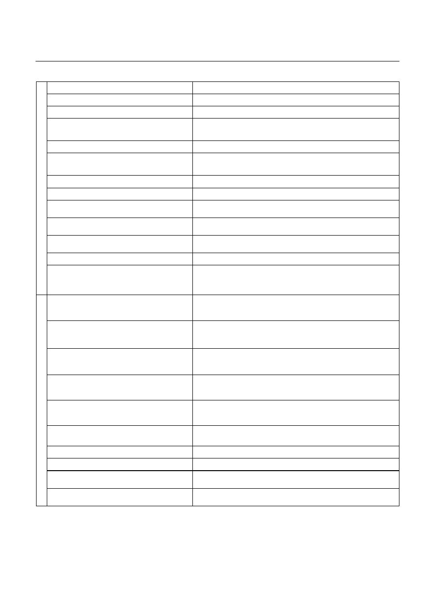
MAJOR INPUT/OUTPUT COMPONENT AND THEIR FUNCTIONS
Speed sensor
Detects output shaft revolution and sends rpm signal to TCM.
Turbine sensor
Detects input shaft revolution and sends rpm signal to TCM.
Engine speed sensor
Inputs engine revolution from engine control computer.
Brake switch
Detects brake pedal operated by the driver and sends signal to
TCM.
Inhibitor switch
Detects select lever position and sends signal to TCM.
Mode select switch
Detects "Power Drive" or "3rd Start" selected by the driver and
sends signal to TCM.
4L switch (4WD Only)
Inputs 4L mode from transfer control computer.
ATF thermo sensor
Detects ATF temperature and sends signal to TCM.
High clutch oil pressure switch
Detects high clutch supply oil pressure and sends signal to
TCM.
2-4 brake oil pressure switch
Detects 2-4 brake supply oil pressure and sends signal to
TCM.
Low & Reverse brake oil pressure switch
Detects low & reverse brake supply oil pressure and signal to
TCM.
Throttle position sensor
Inputs throttle opening angle from engine control computer.
In
pu
t
TCM
Judges necessary line pressure, gear shifting point and lock-up
operation based on electrical signals from switches and
sensors and sends appropriate signals to solenoids.
Line pressure solenoid
Regulates oil pump delivery pressure to the appropriate line
pressure for current driving condition based on signal from
TCM.
Low clutch solenoid
Selects appropriate gear shifting position for current driving
condition and regulates low clutch supply oil pressure based on
signal from TCM.
High clutch solenoid
Selects appropriate gear shifting position for current driving
condition and regulates high clutch supply oil pressure based
on signal from TCM.
2-4 brake solenoid
Selects appropriate gear shifting position for current driving
condition and regulates 2-4 brake supply oil pressure based on
signal from TCM.
Low & Reverse brake solenoid
Selects appropriate gear shifting position for current driving
condition and regulates low & reverse brake supply oil
pressure based on signal from TCM.
Lock-up solenoid
Regulates lock-up pressure to appropriate level for current
driving conditions based on signal from TCM.
Mode indicator lamp
Indicates POWER DRIVE or 3rd START switch position.
Speed meter signal (2WD Only)
Outputs vehicle speed to speed meter.
A/T OIL TEMP indicator lamp
Indicates A/T OIL TEMP indicator lamp in case of high
temperature.
Ou
tput
CHECK TRANS indicator lamp
Indicates CHECK TRANS indicator lamp in case of
malfunction.
CONSTRUCTION AND FUNCTION 7A1-35
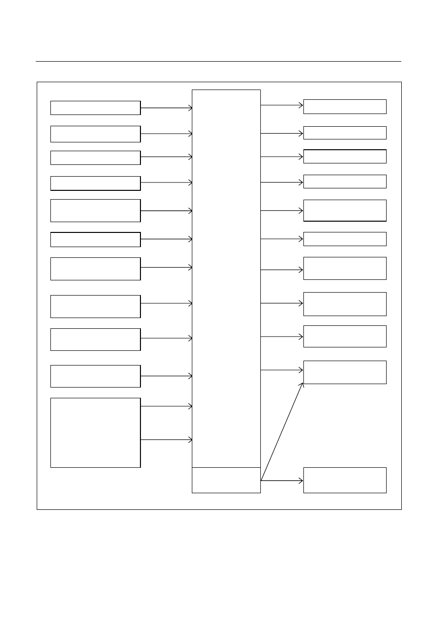
CONTROL CIRCUIT BLOCK DIAGRAM
Speed sensor
Turbine sensor
Brake switch
Inhibitor switch
Power drive, 3rd start
switch
ATF oil thermo sensor
High clutch oil pressure
switch
2-4 brake oil pressure
switch
Low & reverse brake oil
pressure switch
Transfer control module
(4WD Only)
Engine Control Module
(ECM)
Line pressure solenoid
Low clutch solenoid
High clutch solenoid
2-4 brake solenoid
Low & reverse brake
solenoid
Lock-up solenoid
ATF temperature
indicator lamp
Speed meter (2WD
Only)
Power, 3rd start indicator
lamp
Check trans indicator
lamp
Data link connector
Self-diagnosis
function
Transmission
Control
Module
(TCM)
4L mode
Engine
speed
Throttle
angle
Figure 54. Control Circuit Block Diagram
7A1-36 CONSTRUCTION AND FUNCTION
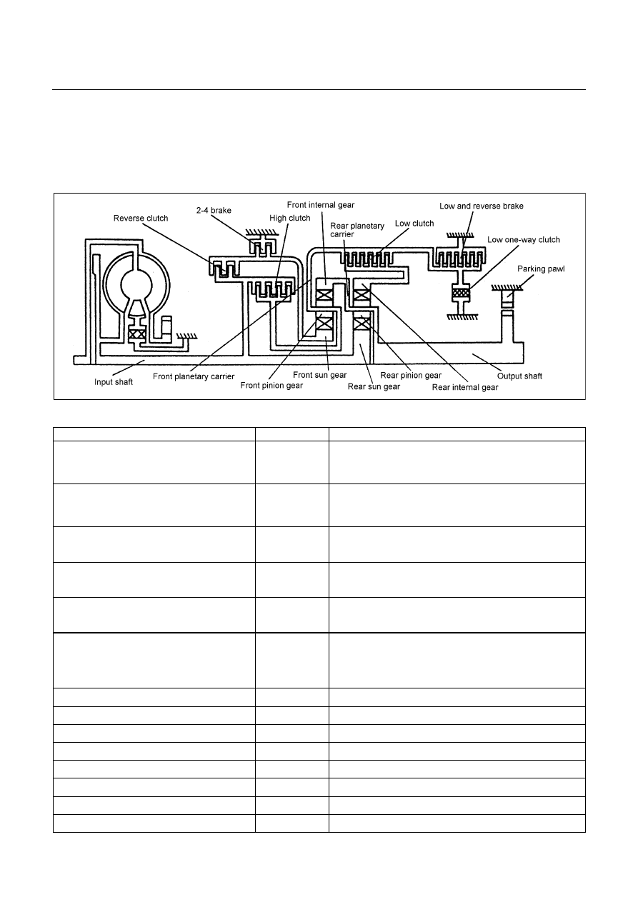
GEAR TRAIN (TRANSMISSION MECHANISM) OPERATION AND
HYDRAULIC CIRCUIT
CONSTRUCTION AND OPERATION
The JR405E consists of two sets of planetary gears, three multiple plate clutches, two multiple plate brakes
and one one-way clutch.
COMPONENT NAME AND FUNCTION
Component Name
Symbol
Function
Low Clutch
L/C
Connects the front planetary carrier to the rear
internal gear.
Engaged at 1st, 2nd and 3rd gear.
High Clutch
H/C
Connects the input shaft to the front planetary
carrier.
Engaged at 3rd and 4th (O/D) gear.
Reverse Clutch
R/C
Connects the input shaft to the front sun gear.
Engaged at Reverse gear.
Low & Reverse Brake
L&R/B
Locks the front planetary carrier.
Engaged at L range and Reverse gear.
2-4 Brake
2-4/B
Locks the front sun gear.
Engaged at 2nd and 4th (O/D) gear.
Low One-way Clutch
L/O.C
Allows the front planetary carrier to turn forward
(clockwise) but locks to opposite direction
(counterclockwise).
Operative when accelerating.
Low Clutch Solenoid
L/C.S
Regulates low clutch pressure.
High Clutch Solenoid
H/C.S
Regulates high clutch pressure.
Low & Reverse Brake Solenoid
L&R/B.S
Regulates low & reverse brake pressure.
2-4 Brake Solenoid
2-4/B.S
Regulates 2-4 brake pressure.
Lock-up Solenoid
L/U.S
Regulates lock-up clutch pressure.
High Clutch Oil Pressure SW
H/C.P/SW
Detects high clutch supply oil pressure.
Low & Reverse Brake Oil Pressure SW
L&R/B.P/SW
Detects low & reverse brake supply oil pressure.
2-4 Brake Oil Pressure SW
2-4/B.P/SW
Detects 2-4 brake supply oil pressure.
CONSTRUCTION AND FUNCTION 7A1-37
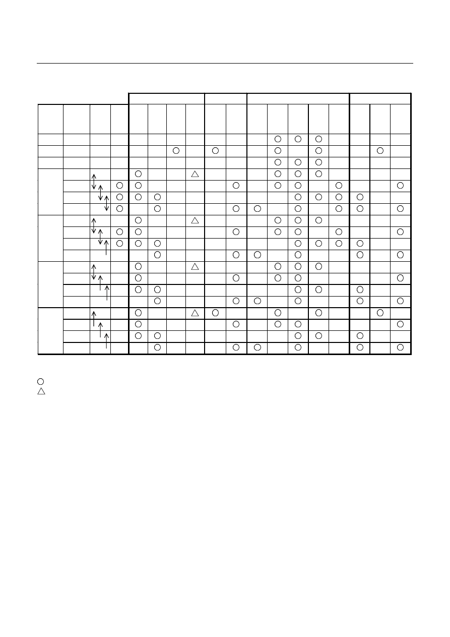
COMPONENT AND THEIR OPERATING CONDITION
Clutch
Brake
Solenoid
Pressure Switch
Select
lever
position
Gear
position
Gear
Shift
Lock-
up
L/C
H/C
R/C
L/O.C
L&R/B
2-4/B
L/C.S
H/C.S
L&R/
B.S
2-4/
B.S
L/U.S
H/
C.P/
SW
L&R/
B.P/
SW
2-4
B.P/
SW
P
-
-
R
Reverse -
N
-
-
1st
2nd
3rd
D
4th
1st
2nd
3rd
3
4th(*1)
1st
2nd
3rd(*1)
2
4th(*1)
1st
2nd(*1)
3rd(*1)
L
4th(*1)
*1:Transmission is shifted at high speed to prevent engine over-run.
- Engaged or operated
- Operative when accelerating
Нет комментариевНе стесняйтесь поделиться с нами вашим ценным мнением.
Текст