Isuzu D-Max / Isuzu Rodeo (TFR/TFS). Manual — part 1739
DIAGNOSIS 7A2-7
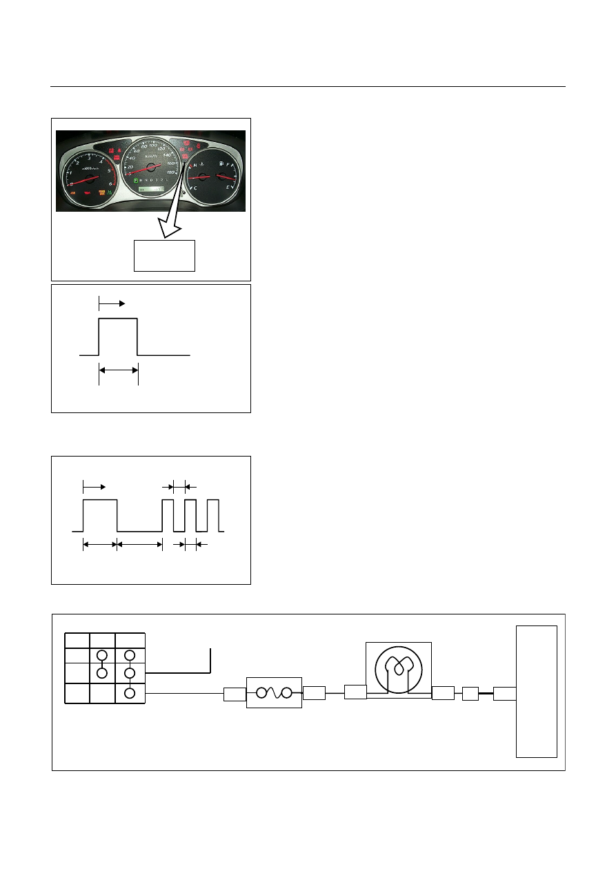
CHECK TRANS INDICATOR & SELF DIAGNOSIS
CHECK
TRANS
Warning to the driver
•
"CHECK TRANS" is ON during 3 seconds at key switch ON
position.
•
When trouble has occurred to electrical components,
"CHECK TRANS" lamp is blinked (1.25 Hz) even during
driving to warn the driver.
•
The trouble is recorded by trouble code in TCM. When
temporary trouble code has been canceled, the "CHECK
TRANS" lamp stops blinking. This blinking can be stopped
by setting the key off. But the trouble code remains
memorized in TCM.
Key SW ON
ON
OFF
3 Sec.
(Lamp Check)
Illumination Pattern at Normal Condition
NOTE:
1. If the "CHECK TRANS" lamp is staying ON always at key
switch ON position, this means that connection between the
lamp and TCM is shorted to ground.
Verify connection and wire between the TCM A20 terminal
and lamp short to ground.
2. If the "CHECK TRANS" lamp is staying OFF at key switch
ON position (Engine off), this means that connection
between the lamp and TCM is opened or meter fuse C5
(15A) is burnt out.
Verify connection and wire between the TCM A20 terminal
and lamp open circuit and meter fuse C5 (15A).
Key SW ON 0.4 Sec.
ON
OFF
3 Sec. 3.2 Sec. 0.4 Sec.
(Lamp Check)
Illumination Pattern at Trouble Condition
Off Acc On V Acc
CHECK TRANS
Meter
Meter Fuse C5 (15A)
Fuse Box & Relay Box
(Cabin)
TCM

7A2-8 DIAGNOSIS
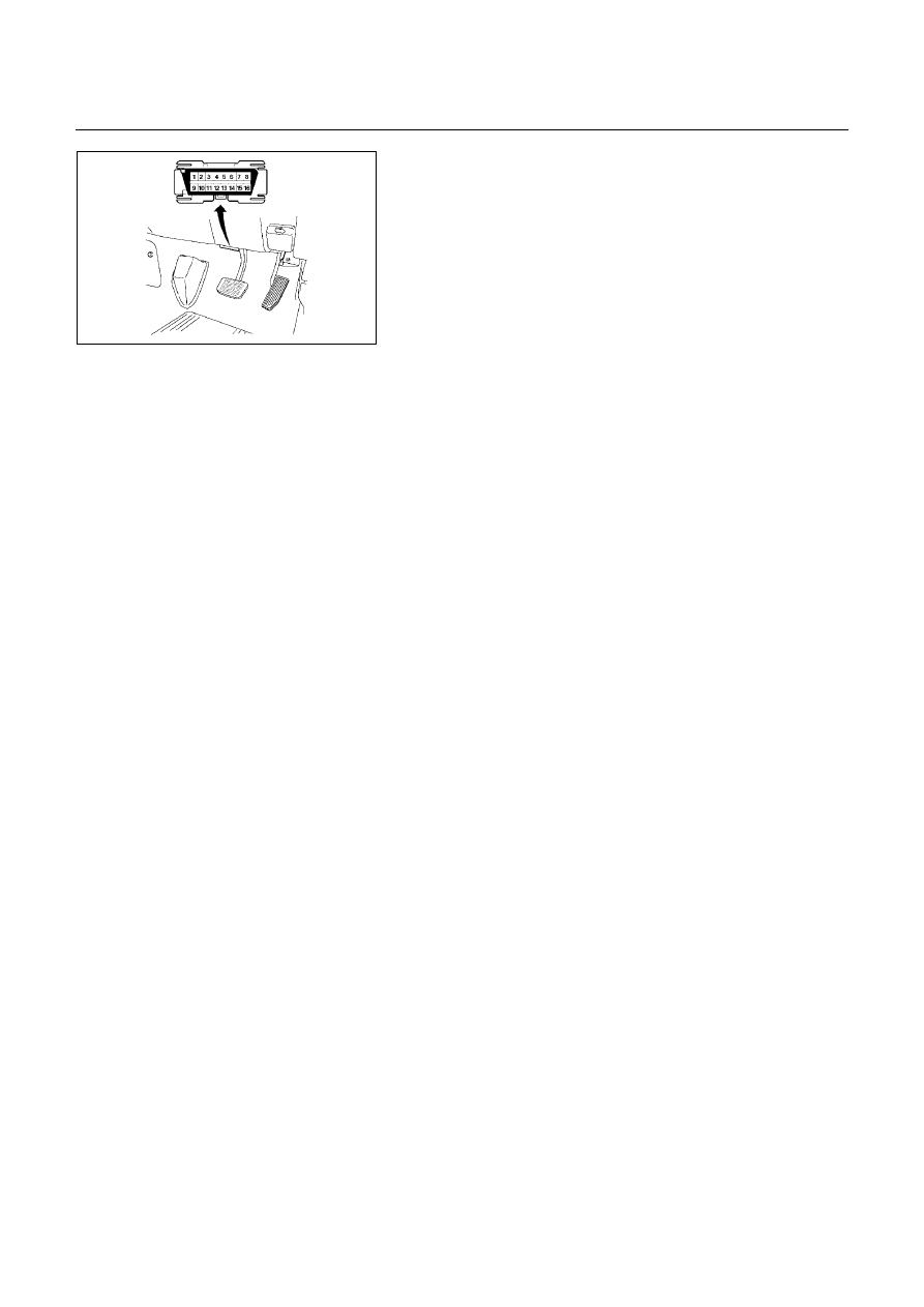
Data Link Connector Short Circuit
Self-diagnosis code (Flash code) display
•
The stored trouble codes can be identified by shorting the
terminal No. 11 and No. 4 or 5 (ground) of data link
connector with a lead wire.
Indication Method:
1.
Terminal No. 11 and No. 4 or 5 (ground) of data link
connector are short circuited.
2.
Turn the key switch to the ON position.
3.
In case no trouble code existence, normal code (12) is
indicated repeatedly.
0.4 Sec 0.4 Sec
.
ON
OFF
3.2 Sec.
1.2 Sec. 3.2 Sec.
0.4 Sec 0.4 Sec
.
ON
OFF
3.2 Sec.
1.2 Sec. 3.2 Sec.
Self-diagnosis Start
Normal Code (12)
Trouble Code (32)
Flash Code Illumination Pattern
4.
In case the plural trouble codes have occurred at a time,
each codes are indicated three rimes in numerical order.
Trouble Code Clear Method:
If you have Tech 2:
Follow the procedure "DIAGNOSIS WITH TECH 2" in this
manual.
If you have no Tech 2:
Remove ECM(B) fuse SBF-4 (30A) for at least 10 seconds.
NOTE:
If you clear the DTC you will not be able to read any codes
recorded during the last occurrence.
To use the DTC again to identify a problem, you will need
to reproduce the fault or the problem. This may require a
new test drive or just turning the key switch on (this
depends on the nature of the fault).
12
14
14
14
32
32
32

DIAGNOSIS 7A2-9
DIAGNOSIS WITH TECH 2
In this JR405E transmission, troubleshooting can be performed for electrical faults using the Tech 2 scan tool.
If the "CHECK TRANS" lamp blinks, or if an electrical fault in the transmission may probably exit, check trouble
codes using the Tech 2 scan tool.
In the diagnostic procedures described in this manual, first repair the faulty positions indicated by trouble code in
order of numbers and then perform troubleshooting for the faulty positions that are not indicated by trouble code.
For correct troubleshooting, it is necessary to first repair the trouble codes of lower order numbers, then to repair
the trouble codes of higher order numbers in sequence.
If no codes are set:
•
Refer to F1: Data Display and identify the electrical faults that are not indicated by trouble code.
•
Refer to "SYMPTOM DIAGNOSIS".
If codes are set:
1.
Record all trouble codes displayed by Tech 2 and check id the codes are intermittent.
2.
Clear the codes.
3.
Drive the vehicle for a test to reproduce the faulty status.
4.
Check trouble codes again using the Tech 2.
5.
If no codes is displayed by test driving, the fault is intermittent. In this case, refer to "INTERMITTENT
DIAGNOSIS".
6.
If a code is present, refer to DTC Chart for diagnosis.
7.
Check trouble codes again using the Tech 2.
TECH 2 CONNECTION
Tech 2 scan tool is used to electrically diagnose the automatic
transmission system and to check the system. The Tech 2
enhances the diagnosis efficiency though all the
troubleshooting can be done without the Tech 2.
1.
Configuration of Tech 2
•
Tech 2 scan tool kit (No. 7000086), Tech 2 scan tool
(No. 7000057) and DLC cable (No. 3000095).
•
SAE 16/19 adapter (No. 3000098) (1), RS232 loop back
connector (No. 3000112) (2) and PCMCIA card (No.
3000117) (3).
2.
Tech 2 Connection
•
Check the key switch is turn OFF.
•
Insert the PCMCIA card (1) into the Tech 2 (4).
•
Connect the SAE 16/19 adapter (2) to the DLC cable (3).
•
Connect the DLC cable (3) to the Tech 2 (4).
•
Connect the SAE 16/19 adapter (2) to the data link
connector of the vehicle.
•
Turn the key switch of the vehicle ON and press the
"PWR" key of the Tech 2.
•
Check the display of the Tech 2.
7A2-10 DIAGNOSIS
NOTE:
Be sure to check that the power is not supplied to the
Tech 2 when attaching or removing the PCMCIA card.
Нет комментариевНе стесняйтесь поделиться с нами вашим ценным мнением.
Текст