Isuzu D-Max / Isuzu Rodeo (TFR/TFS). Manual — part 1021
CAB 10-29
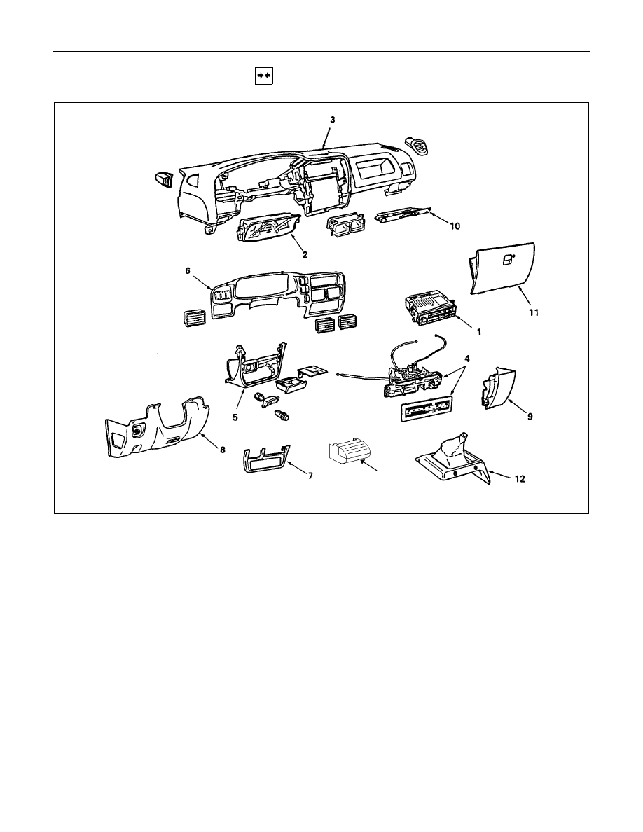
INSTALLATION
12
Installation Steps
1. Radio assembly
2. Meter assembly
3. Instrument panel assembly
▲
4. Control lever assembly
5. Instrument panel lower center cover
assembly
6. Meter cluster assembly
7. Lower cluster assembly
8. Instrument panel driver lower cover
assembly
9. Instrument panel passenger lower cover
assembly
10. Glove box cover
11. Glove box
12. ECM cover (M/T Remote only)
13. Center console assembly
10-30 CAB
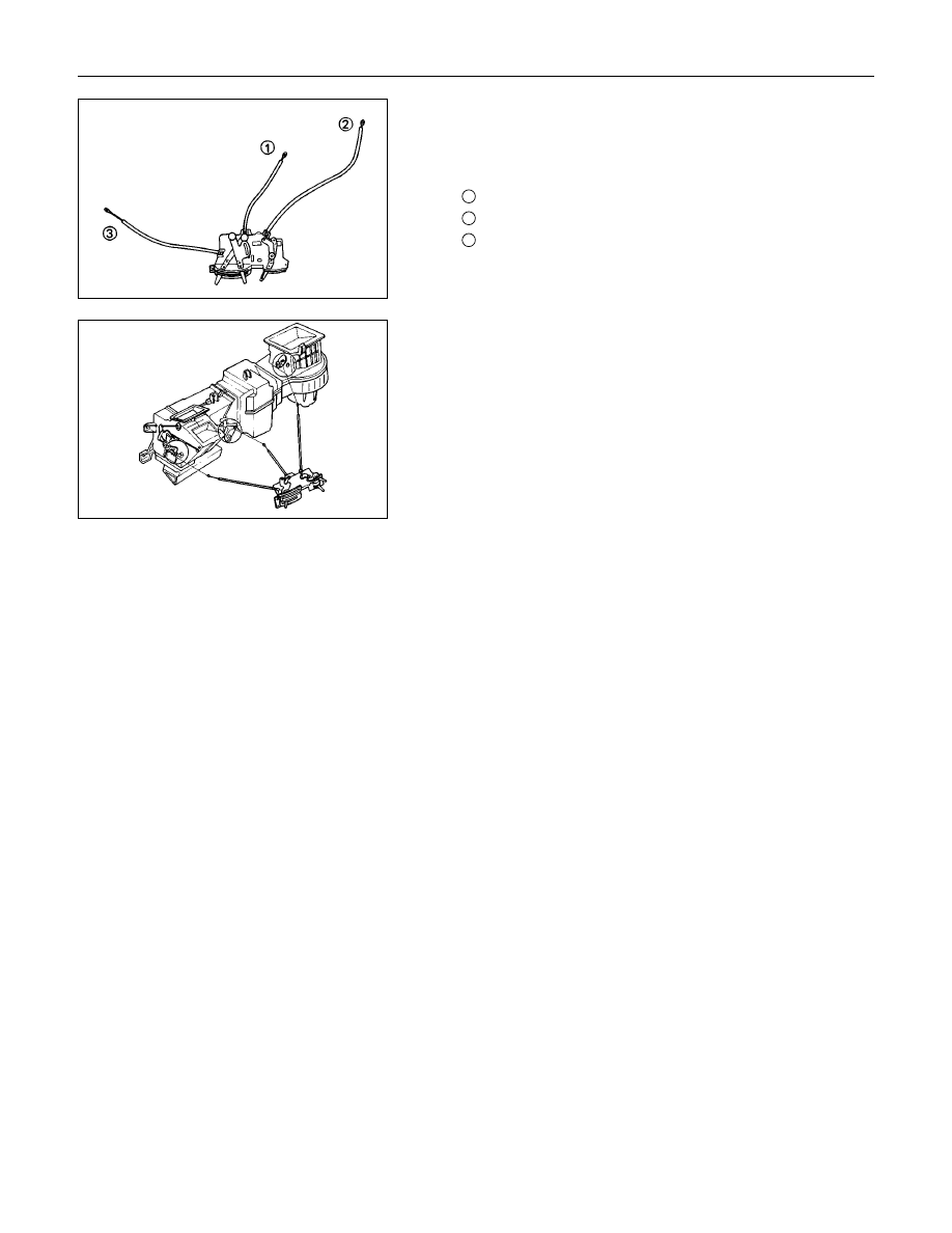
4. Control Lever Assembly
1) Set the temperature control lever and the airsource
select lever at the left-hand side end.
2) Set the air selector lever at the right-hand side end.
1
: Temperature control cable
2
: Air source select cable
3
: Air selector
3) Attach the cable, after the work 1) and 2) have been
completed.
CAB 10-31
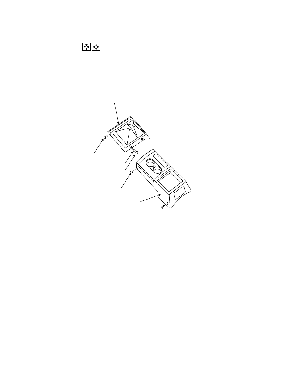
CONSOLE BOX
REMOVAL AND INSTALLATION
6
5
1
2
4
3
4
×
4 S Model
Removal Steps
1. Hole cover
×
2
2. Screw
×
2
3. Screw
×
2
4. Center console
5. Screw
×
4
6. Rear console
Installation Steps
6. Rear console
5. Screw
×
4
4. Center console
3. Screw
×
2
2. Screw
×
2
1. Hole cover
×
2
10-32 CAB
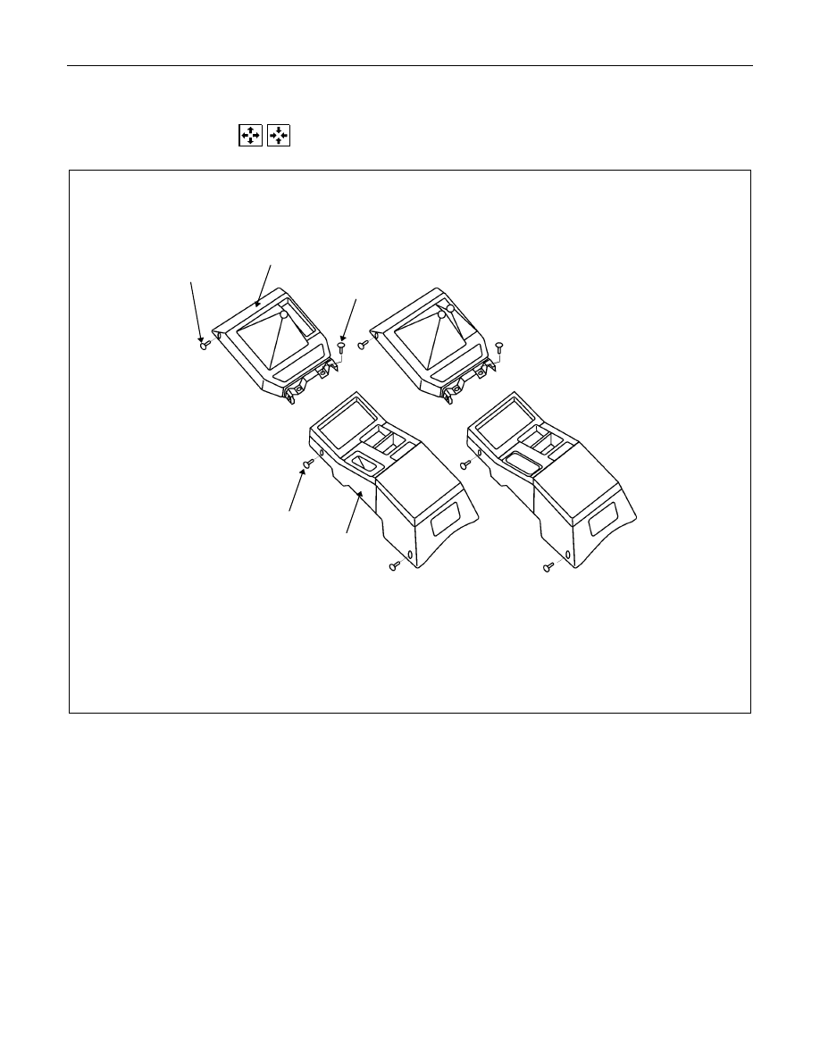
CONSOLE BOX
REMOVAL AND INSTALLATION
4
5
3
2
1
4
×
2 LS Model
4
×
4 LS Model
4
×
2 LS AND 4
×
4 LS Model
Removal Steps
1. Screw
×
4
2. Rear console
3. Screw
×
2
4. Screw
×
2
5. Center console
Installation Steps
5. Center console
4. Screw
×
2
3. Screw
×
2
2. Rear console
1. Screw
×
4
Нет комментариевНе стесняйтесь поделиться с нами вашим ценным мнением.
Текст