Isuzu D-Max / Isuzu Rodeo (TFR/TFS). Manual — part 156

6E–228
4JH1 ENGINE DRIVEABILITY AND EMISSIONS
DIAGNOSTIC TROUBLE CODE (DTC) P1120 (SYMPTOM CODE 1)
(FLASH CODE 21) PEDAL/THROTTLE POSITION SENSOR CIRCUIT HIGH
INPUT
DIAGNOSTIC TROUBLE CODE (DTC) P1120 (SYMPTOM CODE 7)
(FLASH CODE 21) PEDAL/THROTTLE POSITION SENSOR VOLTAGE SUPPLY
CIRCUIT HIGH INPUT
DIAGNOSTIC TROUBLE CODE (DTC) P1120 (SYMPTOM CODE 9)
(FLASH CODE 21) PEDAL/THROTTLE POSITION SENSOR VOLTAGE SUPPLY
CIRCUIT LOW INPUT
DIAGNOSTIC TROUBLE CODE (DTC) P1120 (SYMPTOM CODE D)
(FLASH CODE 21) PEDAL/THROTTLE POSITION SENSOR BRAKE SWITCH
ERROR
DIAGNOSTIC TROUBLE CODE (DTC) P1120 (SYMPTOM CODE E)
(FLASH CODE 21) PEDAL/THROTTLE POSITION SENSOR IDLE POSITION
SWITCH ERROR
0.5
BLK
0.5
GRN/
BLK
69
0.5
RED
49
0.5
WHT
38
0.5
BLK
57
2.0
BLK
1
2.0
BLK
2
0.5
BLK/
PNK
93
0.5
GRY
ECT
Sensor
TPS &
Idle SW
89
0.5
WHT
98
101
0.5
RED
CKP
Sensor
90
IC
IC
IC
IC
Engine
Control
Module
(ECM)

4JH1 ENGINE DRIVEABILITY AND EMISSIONS
6E–229
Condition for setting the DTC and action taken when the DTC sets
Circuit Description
The TPS is a potentiometer connected to throttle shaft
on the throttle body. It is installed to the main TPS and
idle switch.
The engine control module (ECM) monitors the voltage
on the signal line and calculates throttle position. As the
throttle valve angle is changed when accelerator pedal
moved. The TPS signal also changed at a moved
throttle valve. As the throttle valve opens, the output
increases so that the output voltage should be high.
The ECM monitors the TPS supply voltage and TPS
output voltage. The supply voltage is out of range, DTC
P1120 (Symptom Code 7) or P0100 (Symptom Code 9)
will be stored. The output voltage excessively high, DTC
P1120 (Symptom Code 1) will be stored.
If the brake pedal is depressed during accelerator pedal
is depressing, DTC P1120 (Symptom Code D) will be
stored.
If the relation of idle switch and TPS position are
incorrect, DTC P1120 (Symptom Code E) will be stored.
Diagnostic Aids
An intermittent may be caused by the following:
• Poor connections.
• Misrouted harness.
• Rubbed through wire insulation.
• Broken wire inside the insulation.
Check for the following conditions:
• Poor connection at ECM-Inspect harness connectors
for backed out terminals, improper mating, broken
locks, improperly formed or damaged terminals, and
poor terminal to wire connection.
• Damaged harness-Inspect the wiring harness for
damage. If the harness appears to be OK, observe
the “Throttle Position”, “Idle Switch”, “Brake Switch 1”
and “Brake Switch 2” display on the Tech2 while
moving connectors and wiring harness related to the
sensor.
Diagnostic Trouble Code (DTC) P1120 (Symptom Code 1) (Flash Code 21)
Pedal/Throttle Position Sensor Circuit High Input
Flash
Code
Code
Symptom
Code
MIL
DTC Name
DTC Setting Condition
Fail-Safe (Back Up)
21
P1120
1
ON
Pedal/Throttle Position Sen-
sor Circuit High Input
Throttle position sensor out-
put voltage is more than 4.5V.
ECM increases idle speed up
to 1400rpm.
7
ON
Pedal/Throttle Position Sen-
sor Voltage Supply Circuit
High Input
Throttle position sensor power
supply voltage is more than
5.2V.
9
ON
Pedal/Throttle Position Sen-
sor Voltage Supply Circuit
Low Input
Throttle position sensor power
supply voltage is below 4.6V.
D
ON
Pedal/Throttle Position Sen-
sor Brake Switch Error
1. Engine speed is more than
1700rpm.
2. Vehicle speed is more than
1.5km/h.
3. When brake pedal is
depressed during accelera-
tor pedal is depressing.
E
ON
Pedal/Throttle Position Sen-
sor Idle Position Switch Error
1. When idle switch is turned
off, throttle position sensor
was below 0.35%.
or
2. When idle switch is tuned
on, throttle position sensor
was more than 7.8%.
Step
Action
Value(s)
Yes
No
1
Was the “On-Board Diagnostic (OBD) System Check”
performed?
—
Go to Step 2
Go to On Board
Diagnostic
(OBD) System
Check
6E–230
4JH1 ENGINE DRIVEABILITY AND EMISSIONS
2
1. Connect the Tech 2.
2. Review and record the failure information.
3. Select “F0: Read DTC Infor As Stored By ECU” in
“F0: Diagnostic Trouble Codes”.
Is the DTC P1120 (Symptom Code 1) stored as
“Present Failure”?
—
Go to Step 3
Refer to
Diagnostic Aids
and Go to Step
3
3
1. Using the Tech 2, ignition “On” and engine “Off”.
2. Select “F1: Clear DTC Information” in “F0:
Diagnostic Trouble Codes” with the Tech 2 and
clear the DTC information.
3. Operate the vehicle and monitor the “F0: Read
DTC Infor As Stored By ECU” in the “F0:
Diagnostic Trouble Codes”.
Was the DTC P1120 (Symptom Code 1) stored in this
ignition cycle?
—
Go to Step 4
Refer to
Diagnostic Aids
and Go to Step
4
4
Check for poor/faulty connection at the TPS or ECM
connector. If a poor/faulty connection is found, repair
as necessary.
Was the problem found?
—
Verify repair
Go to Step 5
5
Visually check the TPS.
Was the problem found?
—
Go to Step 12
Go to Step 6
Step
Action
Value(s)
Yes
No
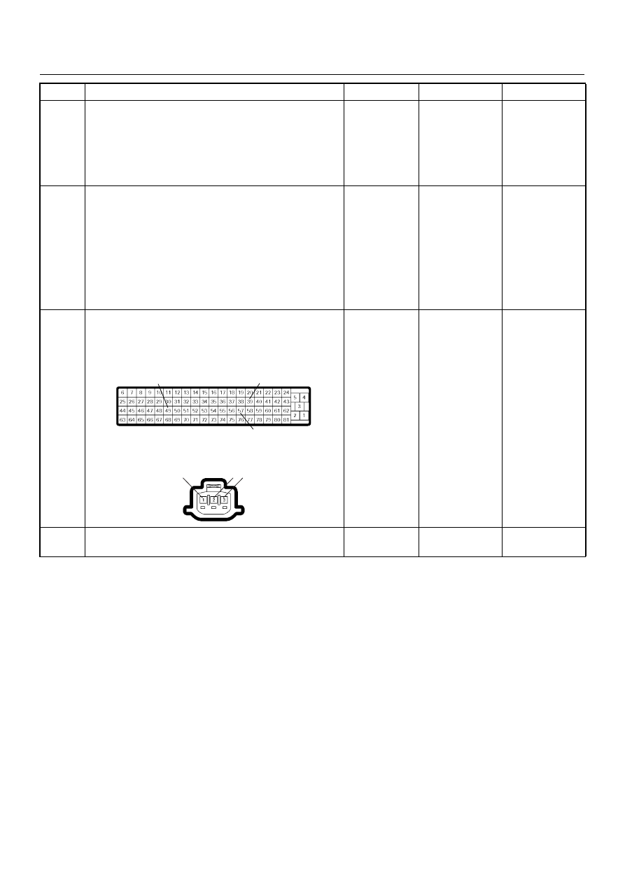
49
39
57
2 3
1
C-56
E-22
4JH1 ENGINE DRIVEABILITY AND EMISSIONS
6E–231
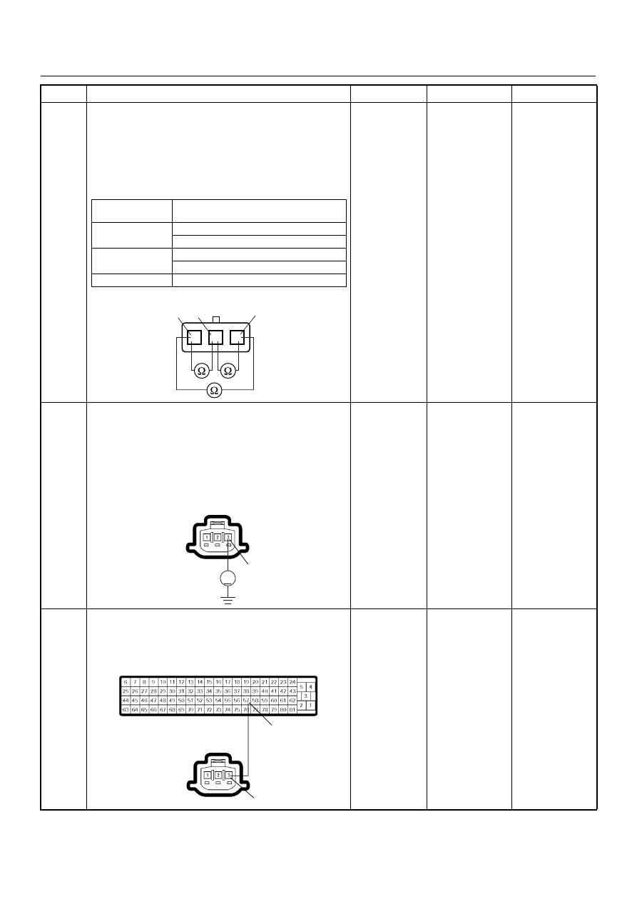
6
Using the DVM and check the TPS.
1. Ignition “Off”, engine “Off”.
2. Disconnect TPS connector.
3. Measure the resistance of TPS.
Does the tester indicate standard resistance as shown
in the following table?
Standard
resistance
Go to Step 7
Go to Step 12
7
Using the DVM and check the TPS power supply
circuit.
1. Ignition “On”, engine “Off”.
2. Disconnect the TPS connector.
3. Check the circuit for short to voltage circuit.
Was the DVM indicated specified value?
Approximately
5.0V
Go to Step 9
Go to Step 8
8
Repair the short to voltage circuit between the ECM
and TPS.
Was the problem solved?
—
Verify repair
Go to Step 14
Step
Action
Value(s)
Yes
No
Measurement
Terminal
Resistance (
Ω)
1 - 2
Approximately 0.5k
Ω at idle position
Approximately 4.0k
Ω at WOT
2 - 3
Approximately 4.3k
Ω at idle position
Approximately 0.8k
Ω at WOT
1 - 3
Approximately 4.6k
Ω at idle position & WOT
TPS
1
2
3
1
2
3
V
3
E-22
57
3
C-56
E-22
Нет комментариевНе стесняйтесь поделиться с нами вашим ценным мнением.
Текст