Isuzu D-Max / Isuzu Rodeo (TFR/TFS). Manual — part 1361
ELECTRICAL-BODY AND CHASSIS 8-9
Solder
Apply 60/40 rosin core solder to the opening in the back of the
clip.
Follow the manufacturer's instructions for the solder equipment
you are using.
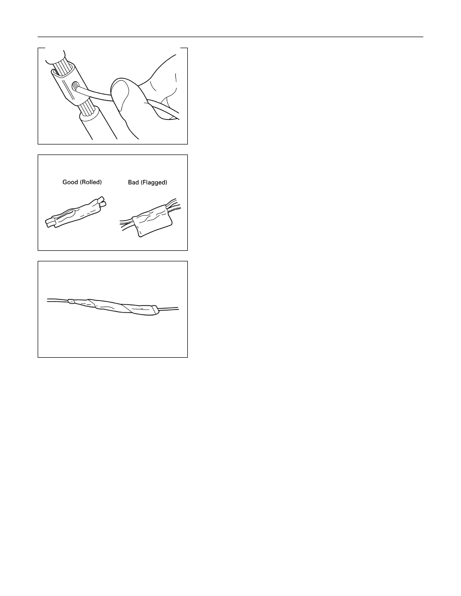
Tape the Splice
Center and roll the splicing tape.
The tape should cover the entire splice.
Roll on enough tape to duplicate the thickness of the insulation
on the existing wires.
Do not flag the tape.
Flagged tape may not provide enough insulation, and the
flagged ends will tangle with the other wires in the harness.
If the wire does not belong in a conduit or other harness
covering, tape the wire again.
Use a winding motion to cover the first piece of tape.
8-10 ELECTRICAL-BODY AND CHASSIS
SYMBOLS AND ABBREVIATIONS
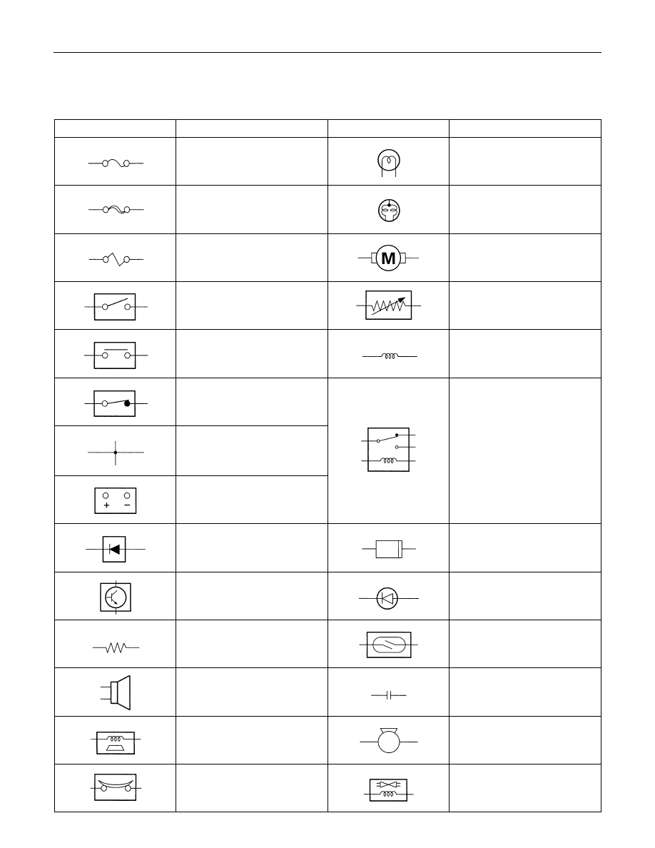
SYMBOLS
Symbol
Meaning of Symbol
Symbol
Meaning of Symbol
Fuse
Bulb
Fusible link
Double filament bulb
Fusible link wire
Motor
Switch
Variable resistor Rheostat
Switch
Coil (inductor),solenoid,
magnetic valve
Switch (Normal close type)
Contact wiring
Relay
Battery
Diode
Connector
Electronic Parts
Light emitting diode
Resistor
Reed switch
Speaker
Condenser
Buzzer
Horn
Circuit breaker
Vacuum switching valve

ELECTRICAL-BODY AND CHASSIS 8-11
ABBREVIATIONS
Abbreviation
Meaning of abbreviation
Abbreviation
Meaning of abbreviation
A
Ampere(S)
LH
Left hand
ABS
Anti-lock brake system
LWB
Long wheel base
ASM
Assembly
MPI
Multiport fuel injection
AC
Alternating current
M/T
Manual transmission
A/C
Air conditioner
OPT
Option
ACC
Accessories
RH
Right hand
CARB
Carburetor
RR
Rear
C/B
Circuit breaker
RWAL
Rear wheel anti-lock brake system
CSD
Cold start device
SRS
Supplemental restraint system
DIS
Direct ignition system
Start
Start
EBCM
Electronic brake control module ST
STD
Standard
ECGI
Electronic control gasoline injection
SW
Switch
ECM
Engine control module
SWB
Short wheel base
ECU
Electronic control unit
TCM
Transmission control module
EFE
Early fuel evaporation
V
Volt
4
×2
Two-wheel drive
VSV
Vacuum switching valve
4
×4
Four-wheel drive
W
Watt(S)
FL
Fusible link
WOT
Wide open throttle
FRT
Front
W/
With
H/L
Headlight
W/O
Without
IC
Integrated circuit
IG
Ignition
kW
kilowatt
8-12 ELECTRICAL-BODY AND CHASSIS
PARTS FOR ELECTRICAL CIRCUIT
WIRING
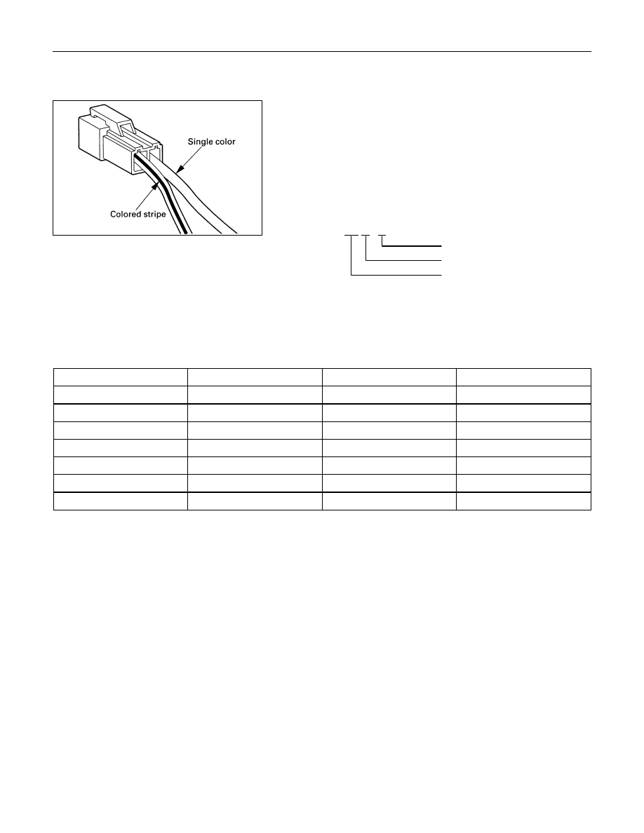
Wire Color
All wires have color-coded insulation.
Wires belonging to system's main harness will have a single
color.
Wires belonging to a system's sub-circuits will have a colored
stripe.
Striped wires use the following code to show wire size and
colors.
Example: 0.5 G / R
Red (Stripe color)
Green (Base color)
Wire size (0.5mm
2
)
Abbreviations are used to indicate wire color within a circuit
diagram.
Refer to the following table.
Wire Color-Coding
Color-Coding
Meaning
Color-Coding
Meaning
B
Black
BR
Brown
W
White
LG
Light green
R
Red
GR
Grey
G
Green
P
Pink
Y
Yellow
LB
Light blue
L
Blue
V
Violet
O
Orange
Нет комментариевНе стесняйтесь поделиться с нами вашим ценным мнением.
Текст