Isuzu D-Max / Isuzu Rodeo (TFR/TFS). Manual — part 247
ENGINE DRIVEABILITY AND EMISSIONS
6E–229
7
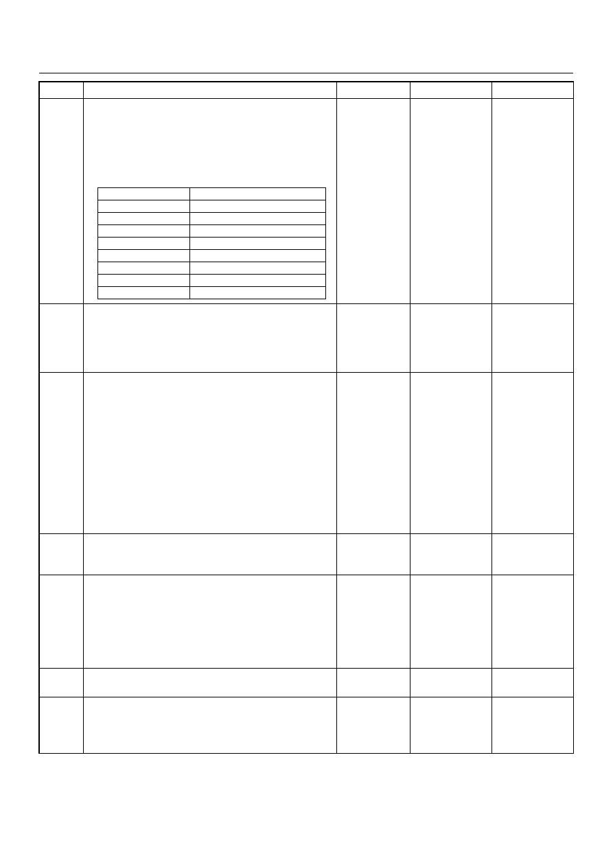
1. Using a Tech 2, display the engine coolant
temperature and note the value.
2. Check the resistance of the engine coolant
temperature sensor.
Is the actual resistance near the resistance value in
the chart for the temperature that was noted?
—
Go to Step 8
Replace the
ECT sensor.
Verify repair
8
1. Using a Tech 2, display the MAP sensor value in
comparison with atmosphere temperature.
2. Check for a faulty, plugged, or incorrectly installed
MAP sensor.
Was the problem found?
—
Verify repair
Go to Step 9
9
Visually/physically inspect all spark plug high-tension
cables. Check for the following conditions:
• Verify that the resistance of all spark plug high-
tension cables are less than the specified value.
• Verify that the all spark plug high-tension cables are
correctly fitted to eliminate cross-fitting.
• Verify that the all spark plug high-tension cables are
not arcing to ground.
Spraying the spark plug high-tension cables with a
light mist of water may help locate an intermittent
problem.
Was a problem found?
#1 cyl. 4.4k
Ω
#2 cyl. 3.6k
Ω
#3 cyl. 3.1k
Ω
#4 cyl. 2.8k
Ω
Verify repair
Go to Step 10
10
Check for proper ignition voltage output with a spark
tester.
Was the problem found?
—
Verify repair
Go to Step 11
11
1. Remove the spark plugs and check for gas or oil
fouling cracks, wear, improper gap, burned
electrodes, heavy deposits, or improper heat
range.
2. If spark plugs are fouled, the cause of fouling must
be determined before replacing the spark plugs.
Was a problem found?
—
Verify repair
Go to Step 12
12
Check for a loose ignition control module ground.
Was a problem found?
—
Verify repair
Go to Step 13
13
1. Check the ignition coil secondary resistance.
2. Replace the coil if it is greater than the specified
resistance.
Did the coil require replacement?
2.5k
Ω
Verify repair
Go to Step 14
Step
Action
Value(s)
Yes
No
Temperature (°C)
Resistance (
Ω) (Approximately)
-20
32040
0
9788
20
3516
40
1439
60
656
80
327
100
175
120
100

6E–230
ENGINE DRIVEABILITY AND EMISSIONS
14
Drain sample fuel, visual inspection.
Any suspecion about the fuel, such as discoloration,
particle, contamination, water, unusual smell, then
drain the fuel from fuel tank.
Replace the fuel from know vehicle source.
If any suspicion of alcohol contamination, completely
drain the fuel, replace by fuel from known vehicle
source.
—
Verify repair
Go to Step 15
15
Perform the procedure in Fuel System Pressure Test
to determine if there is a problem with fuel delivery.
Was a problem found?
—
Verify repair
Go to Step 16
16
1. Check the injector connectors.
2. If any of the connectors are connected at an
improper cylinder, connect as necessary.
Was a problem found?
—
Verify repair
Go to Step 17
17
Check for the following engine mechanical problems
(refer to Engine Mechanical):
• Low compression
• Leaking cylinder head gaskets
• Worn camshaft
• Camshaft drive belt slipped or stripped
Was a problem found?
—
Verify repair
Go to Step 18
18
1. Review all diagnostic procedures within this table.
2. If all procedures have been completed and no
malfunctions have been found, review/inspect the
following:
• Visual/physical inspection
• Tech 2 data
• All electrical connections within a suspected
circuit and/or system
Was a problem found?
—
Verify repair
Go to Step 19
19
Is the ECM programmed with the latest software
release?
If not, download the latest software to the ECM using
the “SPS (Service Programming System)”.
Was the problem solved?
—
Verify repair
Go to Step 20
20
Replace the ECM.
Is the action complete?
IMPORTANT: The replacement ECM must be
programmed. Refer to section of the Service
Programming System (SPS) in this manual.
Following ECM programming, the immobiliser system
(if equipped) must be linked to the ECM. Refer to
section 11 “Immobiliser System-ECM replacement” for
the ECM/Immobiliser linking procedure.
—
Verify Repair
—
Step
Action
Value(s)
Yes
No
ENGINE DRIVEABILITY AND EMISSIONS
6E–231
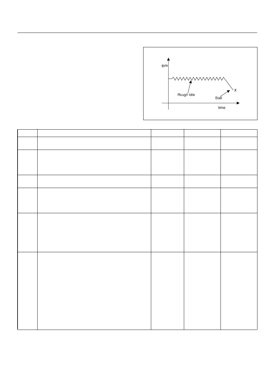
ROUGH, UNSTABLE, OR INCORRECT IDLE, STALLING SYMPTOM
DEFINITIONS: Engine runs unevenly at idle. If severe,
the engine or vehicle may shake. Engine idle speed may
vary in RPM. Either condition may be severe enough to
stall the engine.
Step
Action
Value(s)
Yes
No
1
Was the “On-Board Diagnostic (OBD) System Check”
performed?
—
Go to Step 2
Go to OBD
System Check
2
1. Perform a bulletin search.
2. If a bulletin that addresses the symptom is found,
correct the condition as instructed in the bulletin.
Was a bulletin found that addresses the symptom?
—
Verify repair
Go to Step 3
3
Was a visual/physical check performed?
—
Go to Step 4
Go to Visual /
physical Check.
4
1. Check for faulty, plugged or incorrectly installed
PCV valve.
2. Verify that the PCV system is not plugged.
Was a problem found?
—
Verify repair
Go to Step 5
5
1. Check for incorrect idle speed. Ensure that the
following conditions are present.
• Engine fully warm
• Accessories are “Off”
2. Using a Tech 2, monitor IAC position.
Is the IAC position within the specified values?
20-30 Steps
Go to Step 7
Go to Step 6
6
1. Visually/physically inspect for the following
conditions:
• Restriction of the air intake system. Check for a
restricted air filter element, or foreign objects
blocking the air intake system.
• Check for objects blocking the IAC passage or
throttle bore, excessive deposits in the throttle
bore and on the throttle plate.
• Check for a condition that causes a large
vacuum leak, such as an incorrectly installed or
faulty crankcase ventilation hose/brake booster
hose.
Was a problem found?
—
Verify repair
Go to Step 7
6E–232
ENGINE DRIVEABILITY AND EMISSIONS
7
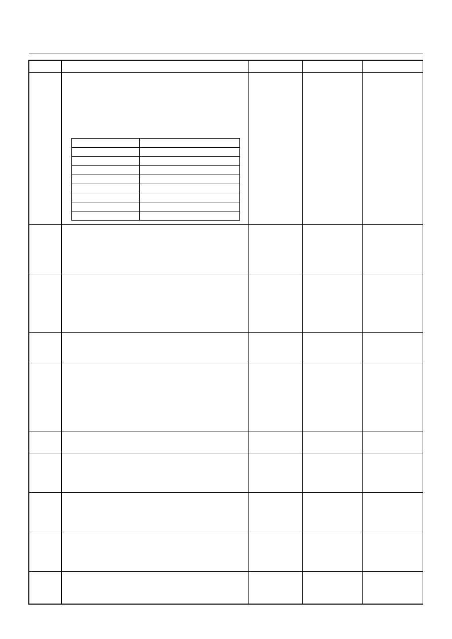
1. Using a Tech 2, display the engine coolant
temperature and note the value.
2. Check the resistance of the engine coolant
temperature sensor.
Is the actual resistance near the resistance value in
the chart for the temperature that was noted?
—
Go to Step 8
Replace the
ECT sensor.
Verify repair
8
1. Using a Tech 2, display the MAP sensor value in
comparison with atmosphere temperature.
2. Check for a faulty, plugged, or incorrectly installed
MAP sensor.
Was the problem found?
—
Verify repair
Go to Step 9
9
Using Tech 2, monitor throttle position with the engine
idling.
Is the throttle position at the specified value and
steady?
0%
Go to Step 10
Refer to
Diagnostic
Trouble Code
P0123 for
further
diagnosis
10
Check for proper ignition voltage output with the spark
tester.
Was a problem found?
—
Verify repair
Go to Step 11
11
1. Remove the spark plugs and check for gas or oil
fouling cracks, wear, improper gap, burned
electrodes, heavy deposits, or improper heat
range.
2. If spark plugs are fouled, the cause of fouling must
be determined before replacing the spark plugs.
Was a problem found?
—
Verify repair
Go to Step 12
12
Check for a loose ignition control module ground.
Was a problem found?
—
Verify repair
Go to Step 13
13
Check items that can cause the engine to run rich.
Refer to DTC P1167 “Fuel Supply System Rich During
Deceleration Fuel Cut Off”.
Was a problem found?
—
Verify repair
Go to Step 14
14
Check items that can cause the engine to run lean.
Refer to DTC P1171 “Fuel Supply System Lean
During Power Enrichment”.
Was a problem found?
—
Verify repair
Go to Step 15
15
Check the injector connectors, if any of the injectors
are connected any incorrect cylinder, correct as
necessary.
Was a problem found?
—
Verify repair
Go to Step 16
16
1. Check for faulty engine mounts.
2. If a problem is found, repair as necessary.
Was a problem found?
—
Verify repair
Go to Step 17
Step
Action
Value(s)
Yes
No
Temperature (°C)
Resistance (
Ω) (Approximately)
-20
32040
0
9788
20
3516
40
1439
60
656
80
327
100
175
120
100
Нет комментариевНе стесняйтесь поделиться с нами вашим ценным мнением.
Текст