Isuzu D-Max / Isuzu Rodeo (TFR/TFS). Manual — part 97

4JA1-TC/4JH1-TC ENGINE DRIVEABILITY AND EMISSIONS
6E–383
24
Replace the ECM.
Is the action complete?
IMPORTANT: The replacement ECM must be
programmed. Refer to section of the Service
Programming System (SPS) in this manual.
Following ECM programming, the immobiliser system
(if equipped) must be linked to the ECM. Refer to
section 11 “Immobiliser System-ECM replacement” for
the ECM/Immobiliser linking procedure.
—
Verify repair
—
25
Replace the injection pump assembly.
Is the action complete?
—
Verify repair
—
Step
Action
Value(s)
Yes
No
6E–384
4JA1-TC/4JH1-TC ENGINE DRIVEABILITY AND EMISSIONS
ON-VEHICLE SERVICE PROCEDURE
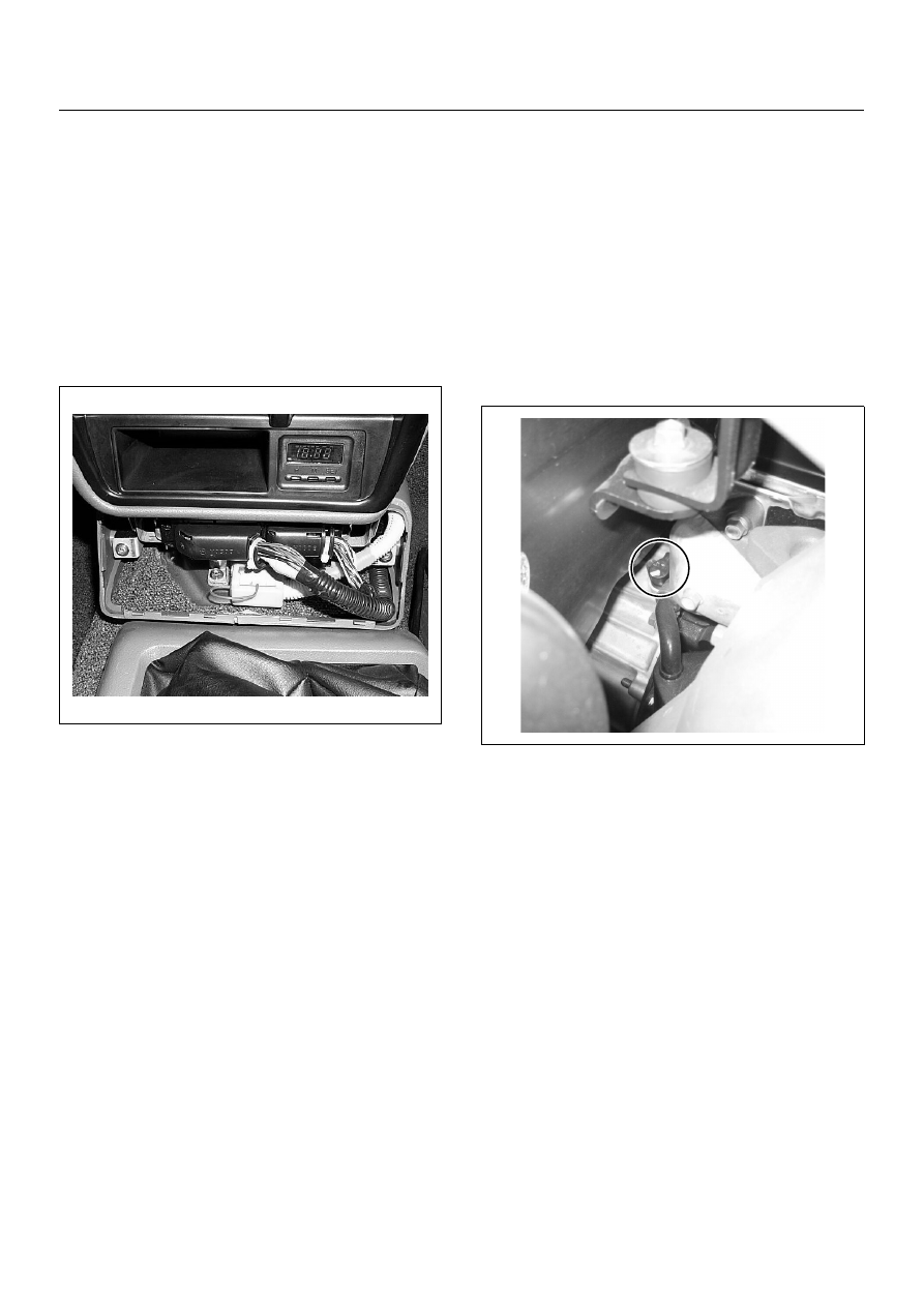
ENGINE CONTROL MODULE (ECM)
Location
Upper the transmission tunnel.
Removal Procedure
1. Disconnect the negative battery cable.
2. Remove the ECM cover.
3. Disconnect the two connectors from the ECM.
4. Remove four screws from the ECM braket.
Installation Procedure
1. Put on the ECM to the braket and tighten by four
screws.
2. Connect the two connectors to the ECM.
3. Refit the ECM cover by four screws.
4. Connect the negative battery cable.
NOTE: The replacement ECM must be programmed.
Refer to section of the Service Programming System
(SPS) in this manual.
Following ECM programming, the immobiliser system (if
equipped) must be linked to the ECM. Refer to section
11 “Immobiliser System-ECM replacement” for the
ECM/Immobiliser linking procedure.
CRANKSHAFT POSITION (CKP)
SENSOR
Location
Installed to the clutch housing.
Removal Procedure
1. Disconnect the negative battery cable.
2. Disconnect connector from the CKP sensor.
3. Loosen a bolt and remove the CKP sensor from the
clutch housing.
Installation Procedure
1. Install the CKP sensor to the clutch housing.
2. Tighten CKP sensor by a bolt with specified
tightening torque.
Tightening Torque
• Bolts: 8.0 - 12.0 N·m (0.8 - 1.2 kgf·m)
3. Connect a CKP sensor connector to the CKP
sensor.
4. Connect the negative battery cable.
NOTE: Verify any DTCs (diagnosis Trouble Code) are
not stored after replacement.
4JA1-TC/4JH1-TC ENGINE DRIVEABILITY AND EMISSIONS
6E–385
ENGINE COOLANT TEMPERATURE
(ECT) SENSOR
Location
Installed to the thermostat housing.
Removal Procedure
1. Disconnect the negative battery cable.
2. Drain enough engine coolant so that the coolant
level will be below the ECT sensor.
3. Disconnect connector from the ECT sensor.
4. Loosen and remove the ECT sensor from the
thermostat housing.
NOTE: Cool down the engine before above procedures
are carried out.
Installation Procedure
1. Apply sealer to threads of screw at the ECT sensor.
2. Tighten the ECT sensor with specified tightening
torque.
Tightening Torque
• Bolt: 13N·m (1.3kgf·m)
3. Connect a ECT sensor connector to the ECT
sensor.
4. Fill the engine coolant.
5. Connect the negative battery cable.
NOTE: Verify any DTCs (diagnosis Trouble Code) are
not stored after replacement.
Verify no engine coolant leaking from the sensor
threads after replacement.
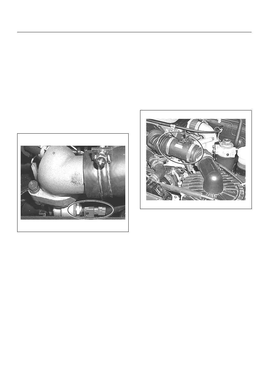
MASS AIR FLOW (MAF) & INTAKE
AIR TEMPERATURE (IAT) SENSOR
Location
Installed to the intake duct housing.
Removal Procedure
1. Disconnect the negative battery cable.
2. Disconnect a MAF & IAT sensor connector from the
MAF & IAT sensor assembly.
3. Loosen the clips and remove the MAF & IAT sensor
assembly from the intake duct housing.
Installation Procedure
1. Install the MAF & IAT sensor assembly into intake
air duct.
2. Tighten the clips.
3. Connect a MAF & IAT sensor connector to the MAF
& IAT sensor assembly.
4. Connect the negative battery cable.
NOTE: Verify any DTCs (diagnosis Trouble Code) are
not stored after replacement.
6E–386
4JA1-TC/4JH1-TC ENGINE DRIVEABILITY AND EMISSIONS
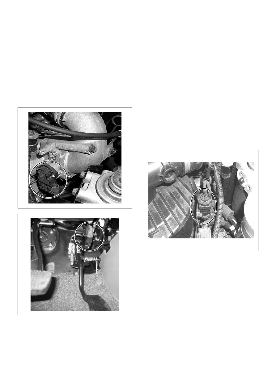
PEDAL/THROTTLE POSITION
SENSOR (TPS)
Location
Installed on the throttle body.
Removal Procedure
1. Disconnect the negative battery cable.
2. Disconnect the TPS connector.
3. Loosen two screws and remove TPS from the
throttle body.
Installation Procedure
1. Temporary tighten the TPS by two screws.
2. Connect a TPS connectors to the TPS.
3. Connect the Tech2 to the vehicle.
4. Connect the negative battery cable.
5. Select “Data Display” with the Tech2.
6. Check the throttle position data and adjust the TPS
position.
7. Tighten two screws.
NOTE: Verify any DTCs (diagnosis Trouble Code) are
not stored after replacement.
EGR EVRV (Electrical Vacuum
Regulating Valve)
Location
Back of the air cleaner case.
Removal Procedure
1. Disconenct the negative battery cable.
2. Disconnect a EVRV connector from the EVRV.
3. Disconnect two hoses from the EVRV.
4. Loosen two bolts and remove the EVRV from the
bracket.
Installation Procedure
1. Tighten the purge solenoid by tow bolts.
2. Connect a connector to the EVRV.
3. Connect two hoses to the EVRV.
4. Connect the negative battery cable.
NOTE: Verify any DTCs (diagnosis Trouble Code) are
not stored after replacement.
Verify proper connection of two hoses.
Нет комментариевНе стесняйтесь поделиться с нами вашим ценным мнением.
Текст