Isuzu D-Max / Isuzu Rodeo (TFR/TFS). Manual — part 1693

6A-70 ENGINE MECHANICAL (C24SE, C22NE, 22LE, 20LE)
ENGINE EXTERNAL PARTS
Radiator
Removal
1.
Remove the upper hose and lower hose.
2.
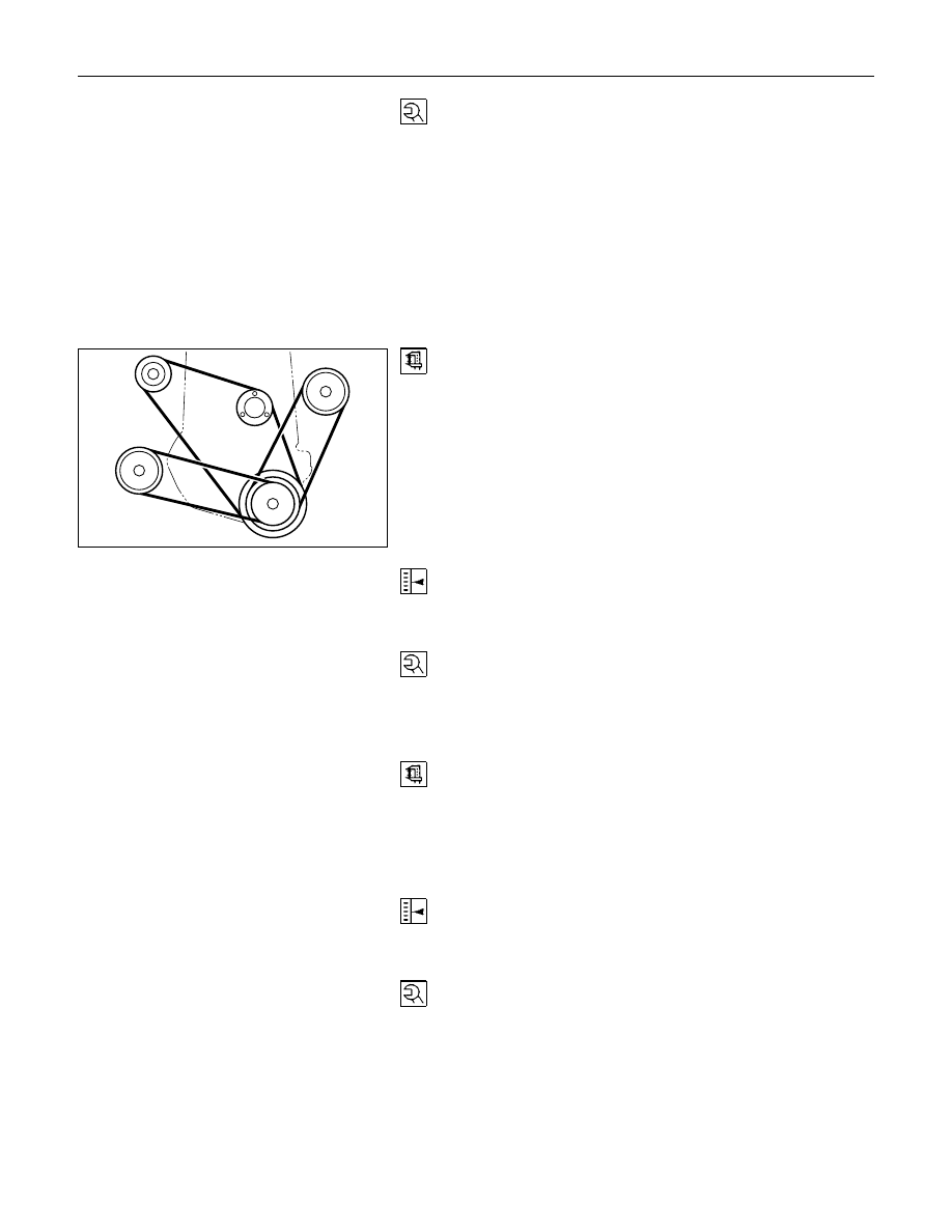
Remove all V-belts.
3.
Remove the cooling fan.
4.
Remove the fan guide.
5.
Remove the radiator.
Installation
1.
Install the radiator.
2.
Install the fan guide.
3.
Install the cooling fan.
4.
Install all V-belts.
5.
Install the lower and upper hose.
Thermostat
Removal
1.
Remove water outlet nozzles with thermostat from
thermostat housing.
2.
Remove coolant hose and collect coolant.
Important!
Remove and Install thermostat only together with water outlet
nozzles.
Tighten (Torque)
Water outlet nozzles to thermostat housing - 8 N
⋅m (0.8 kgf⋅m)
Installation
1.
Install coolant hose.
2.
Fill cooling system and bleed according to the
corresponding operation.

ENGINE MECHANICAL (C24SE, C22NE, 22LE, 20LE) 6A-71
Water Pump
Removal
1.
Remove lower hose band from pipe band and collect
coolant.
2.
Remove front toothed belt cover according to the
corresponding operation.
3.
Remove water pump from cylinder block after releasing
tension on toothed belt.
Clean
Sealing surfaces
Coating sealing surfaces with Silicone Grease
Installation
1.
Install water pump to cylinder block with new rubber O-
ring.
2.
Apply tension to toothed belt according to the
corresponding operation.
3.
Install coolant hoses.
4.
Fill cooling system and bleed according to the
corresponding operation.
Alternator
Removal
1.
Remove ground cable from battery.
2.
Remove cable connection from alternator and V-belt.
3.
Remove alternator from retaining strap and lower
fastening.
Installation
1.
Install alternator by tightening firmly by hand.
2.
Install V-belt and apply tension according to the
corresponding operation.
3.
Install cable connections to alternator.
4.
Install ground cable to battery.
Starter
Removeal
1.
Remove cable connections from starter.
2.
Remove upper bolt of transmission side.
3.
Remove lower bolt of engine side.
6A-72 ENGINE MECHANICAL (C24SE, C22NE, 22LE, 20LE)
Tighten (Torque)
Starter to cylinder block:
Engine side - 45 N
⋅m (4.6 kgf⋅m)
Transmission side - 75 N
⋅m (7.6 kgf⋅m)
Starter support to cylinder block - 25 N
⋅m (2.5 kgf⋅m)
Re-connect cables.
V-belt Tension of Alternator
Measure
Measure V-belt tension of alternator.
Permitted values for new V-belt are approx. 311-489N (31-50
kgf).
Note:
V-belt to deflection as loaded with 10kg : 8-12mm.
Adjust
Adjust V-belt tension by loosening clamping bracket and lower
alternator bracket and moving alternator.
Tighten (Torque)
Clamping bracket to alternator - 25 N
⋅m (2.6 kgf⋅m)
Lower alternator bracket - 25 N
⋅m (2.6 kgf⋅m)
V-Belt Tension of Power Steering Pump
Measure
Measure V-belt tension of power steering pump. Permitted
values for new belt are approx. 578-712N (59-73 kgf) and 534-
667N (54-68 kgf) for used belt.
Note:
V-belt to deflection as loaded with 10kg : 8-12mm.
Adjust
Adjust V-belt tension by loosening clamping bolt, lower pump
bracket, and adjusting nuts and moving steering pump.
Tighten (Torque)
Adjusting nuts - 18 N
⋅m (1.8 kgf⋅m)
Clamping bolt - 25 N
⋅m (2.6 kgf⋅m)
Lower pump bracket - 26 N
⋅m (2.6 kgf⋅m)
ENGINE MECHANICAL (C24SE, C22NE, 22LE, 20LE) 6A-73
FUEL INJECTION SYSTEM
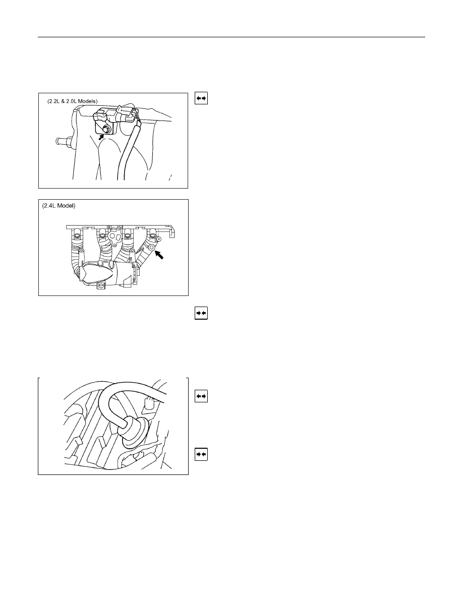
MAP SENSOR
Removal
1.
Disconnect the battery cable.
2.
Disconnect the electrical connector from the sensor.
3.
Remove the mounting bolts securing the sensor to the
manifold.
4.
Remove the sensor from the intake manifold.
Installation
1.
Push MAP sensor into the manifold.
2.
Install the mounting bolts and tighten them.
3.
Connect electrical connector.
4.
Connect the battery cable.
Pressure Regulator
Removal
1.
Remove vacuum hose.
2.
Remove fuel hoses.
3.
Remove pressure regulator.
Installation
1.
Install pressure regulator.
2.
Install fuel hoses.
3.
Install vacuum hoses.
Нет комментариевНе стесняйтесь поделиться с нами вашим ценным мнением.
Текст