Isuzu D-Max / Isuzu Rodeo (TFR/TFS). Manual — part 1121
ELECTRICAL-BODY AND CHASSIS 8-241
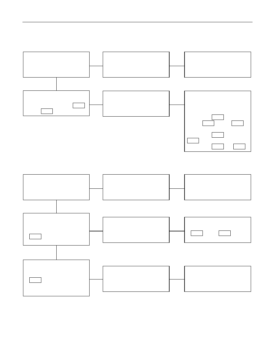
2. Even when the parking brake lever is pulled, the indicator light does not go off
Checkpoint
Trouble Cause
Countermeasure
Adjust the SW. installation
position or replace the parking
brake SW.
Incorrect the parking brake
SW. adjustment or brake SW.
faulty
NG
Thermo unit malfunction
Replace the brake fluid level
SW., or vacuum SW., or
repair a short circuit between
the parking brake SW.
connector 1
C-39
(4
×4: 1
R-4
) and 12
B-23
or the brake fluid level SW.
connector 3
C-37
and 12
B-23
, or the vacuum SW.
connector 1
C-38
and
B-23
Check to see if the indicator
light goes off when the parking
brake SW. connector 1
C-39
(4
×4: 1
R-4
) is disconnected
Brake fluid level SW. or
vacuum SW. faulty or short
circuit
NG
OK
Parking brake SW. installation
position and function
3. Oil pressure warning light does not go off while engine is running
Refer to ENGINE Section
Refer to ENGINE Section
NG
Thermo unit malfunction
Repair a short circuit between
1
P-11
and 10
B-23
Check to see the warning light
goes off when the oil pressure
SW. connector
1
P-11
is disconnected
Short circuit
Replace the oil pressure unit
(or the oil pressure SW.)
Continuity between the oil
pressure SW. connector
1
P-11
and the body ground
when the engine is operating
Oil pressure unit (or oil
pressure SW) faulty
NG
NG
OK
OK
Engine oil pressure
8-242 ELECTRICAL-BODY AND CHASSIS
REMOVAL AND INSTALLATION
METER ASSEMBLY
Removal
1. Instrument Panel Driver Lower Cover
• Refer to the removal steps of “INSTRUMENT PANEL” in
Section 10 “CAB”.
2. Lower Cluster Assembly
• Refer to the removal steps of “INSTRUMENT PANEL” in
Section 10 “CAB”.
3. Instrument Panel Cluster Assembly
• Refer to the removal steps of “INSTRUMENT PANEL” in
Section 10 “CAB”
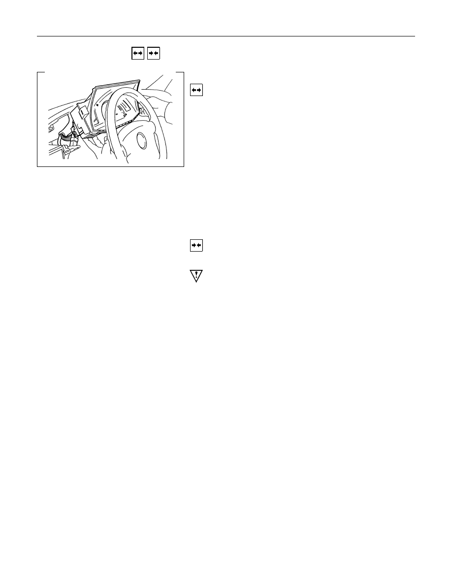
4. Meter Assembly
• Remove four screws of the meter assembly.
• Disconnect the meter connectors.
Installation
Follow the removal procedure in the reverse order to install the
meter.
Pay close attention to the important points mentioned in the
following paragraphs.
Connector
Be absolutely sure that the meter connectors are securely
connected.
This will prevent a poor contact and an open circuit.
Wire Harness
Do not pinch the wire harness between the cluster and the
meter hood during the meter assembly installation procedure.
Wire damage will result.
ELECTRICAL-BODY AND CHASSIS 8-243
METERS AND GAUGES
Removal
1. Meter Assembly
• Refer to “METER ASSEMBLY” removal steps in this
system.
2. Meter Glass
3. Meter Needless
• Pull out the needles of speedometer and tachometer
4. Meter Board
• Loosen four fixing screws.
5. Meters and Gauges
Installation
To Install, follow the removal steps in the reverse order.
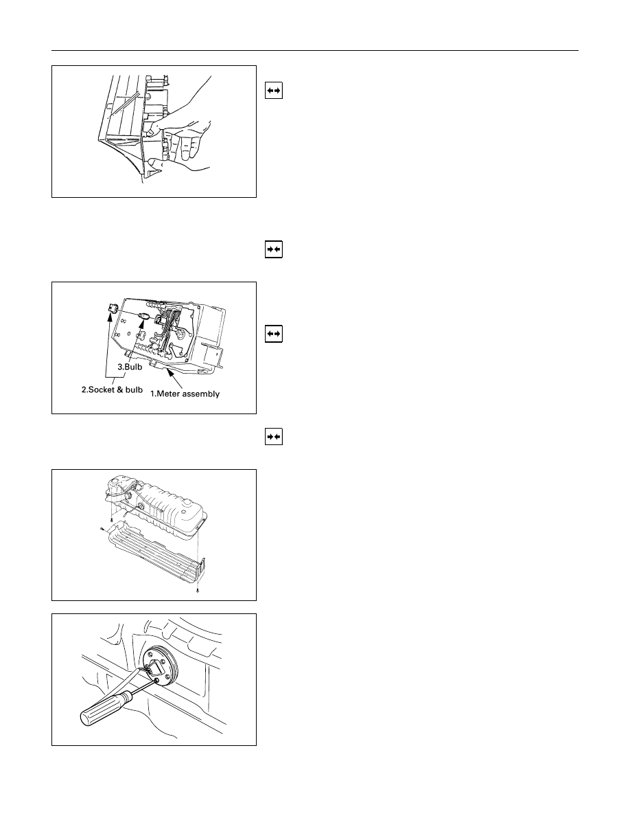
WARNING LIGHT BULB, INDICATOR
LIGHT BULB AND ILLUMINATION LIGHT
BULB
Removal
Turn the bulb socket counterclockwise and pull the bulb out.
Installation
To Install, follow the removal steps in the reverse order.
FUEL TANK UNIT
Removal
Dismount the fuel tank first, then remove the fuel tank unit.
1. Disconnect the fuel tank unit connector.
2. Loosen the screws.
3. Remove the fuel tank unit from the fuel tank.
8-244 ELECTRICAL-BODY AND CHASSIS
Installation
Follow the removal procedure in the reverse order to install the
fuel tank unit.
Pay close attention to the important points mentioned in the
following paragraphs.
Rubber Seal
Be absolutely sure that the fuel tank unit rubber seal is
correctly seated.
Connector
Be absolutely sure that the fuel tank unit connector is securely
connected.
This will prevent a poor contact and an open circuit.
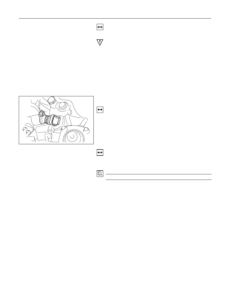
VEHICLE SPEED SENSOR (INSTALLED
ON THE TRANSMISSION)
Removal
1. Disconnect the connector.
2. Remove the vehicle speed sensor body by rotating it.
Installation
To Install, follow the removal steps in the reverse order, noting
the following point.
Tighten the vehicle speed sensor to the specified torque.
Vehicle Speed Sensor Tightening Torque
N
⋅m (kgf⋅m/lb.ft)
25
± 4.9 (2.5 ± 0.5/18 ± 3.6)
Нет комментариевНе стесняйтесь поделиться с нами вашим ценным мнением.
Текст