Isuzu D-Max / Isuzu Rodeo (TFR/TFS). Manual — part 1731
CONSTRUCTION AND FUNCTION 7A1-21
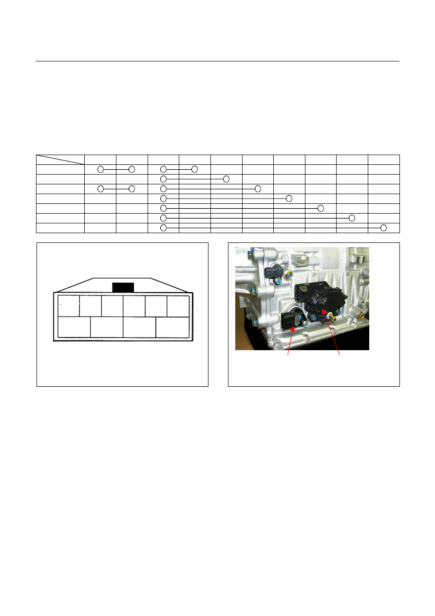
INHIBITOR SWITCH
•
The inhibitor switch is installed on the right side of the transmission main unit to detect the select lever
position.
•
The inhibitor switch is connected with the starter SW circuit. The engine cannot be started when the
select lever is at any position other than the P or N range.
•
By moving the select lever, the combination of the inhibitor switch pins is changed. The current range of
TCM is detected based on the combination of the pins.
10 7 3 2 4 8 5 1 9 6
P
R
N
D
3
2
L
6
3
4
5
10
9
8
7
2
1
Terminal Assembly
Inhibitor Switch
Figure 36. Pin Assignment
Figure 37. Location of Inhibitor Switch
7A1-22 CONSTRUCTION AND FUNCTION
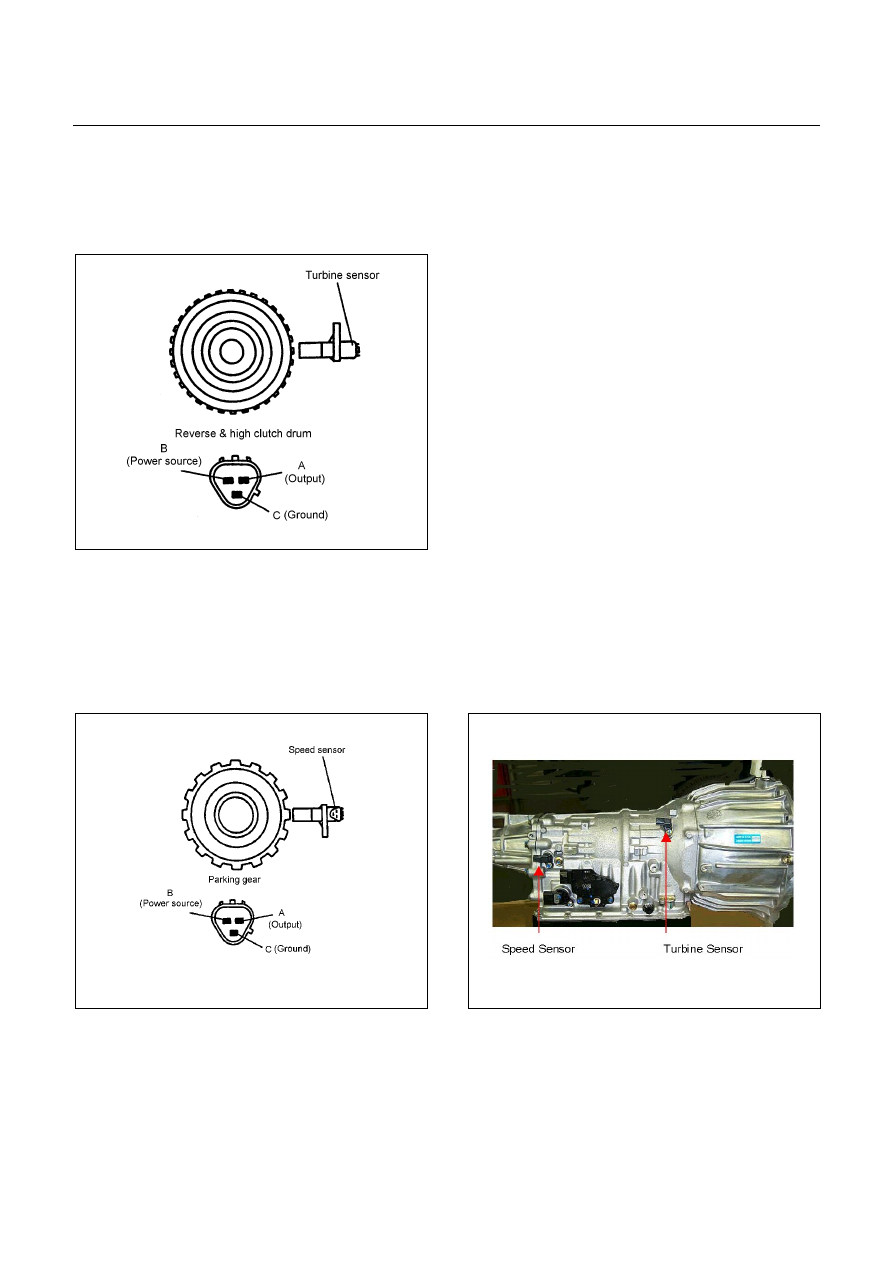
TURBINE SENSOR
•
The turbine sensor is a hall element. It is installed to the front of the transmission case. The turbine
sensor converts the rotations of the reverse & high clutch drum fitted with the input shaft by spline to
pulse signal and sends the signal to TCM.
•
One turn of the reverse & high clutch drum generates 32-pulse signal, which is sent to the TCM.
Figure 38. Turbine Sensor
SPEED SENSOR
•
The speed sensor is a hall element. It is installed to the rear of the transmission case. The speed sensor
converts the rotations of the parking gear fitted with the output shaft by spline to a pulse signal which is
sent to the TCM.
•
One turn of the parking gear generates a 16-pulse signal to be sent to the TCM.
Figure 39. Speed Sensor
Figure 40. Location of Turbine & Speed Sensor
CONSTRUCTION AND FUNCTION 7A1-23
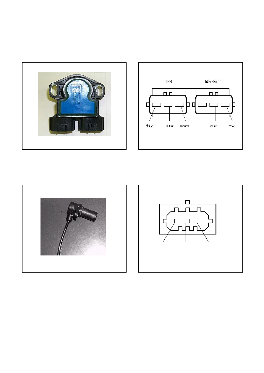
THROTTLE POSITION SENSOR (TPS)
•
Opening of the accelerator pedal is converted to an electric signal which is transmitted from ECM to TCM.
Figure 41. Throttle Position Sensor
Figure 42. Pin Assignment
ENGINE SPEED SENSOR (=TDC SENSOR)
•
The engine speed sensor converts the crankshaft from the TDC (Top Dead Center) sensor rotation to a
pulse signal which is transmitted from ECM to TCM.
Ground
Signal
Shield Line
Figure 43. TDC Sensor
Figure 44. Pin Assignment
7A1-24 CONSTRUCTION AND FUNCTION
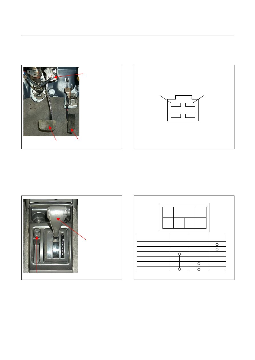
BRAKE SWITCH
•
The brake switch is installed to the brake pedal. When the driver steps on the brake pedal, an electric
signal is sent to the TCM.
Brake Switch
Accelerator Pedal
Brake Pedal
TCM A3
+12V
Figure 45. Brake Switch
Figure 46. Pin Assignment
MODE SELECT SWITCH
•
The mode select switch is installed beside the select lever. When the driver selects the PWR or 3rd, an
electric signal is sent to the respectively. It turns ON the indicator lamp in the meter.
•
The 3rd START mode can be used only in the D range.
Mode Select Switch
Gear Select Lever
Power 3rd
Illumination
Lamp
1 (Illumination)
2 (Ground)
3 (TCM A24)
4 (No Connection)
5 (TCM A11)
6 (Ground)
2
1
6
5
4
3
Figure 47. Mode Select Switch
Figure 48. Pin Assignment
Нет комментариевНе стесняйтесь поделиться с нами вашим ценным мнением.
Текст