Isuzu D-Max / Isuzu Rodeo (TFR/TFS). Manual — part 370

7A-28 AUTOMATIC TRANSMISSION (AW30-40LE)
Circuit Description:
Vehicle speed information is provided to the TCM by
the vehicle speed sensor 2. This sensor is located in
the transmission extension housing (4×2) or adapter
housing (4×4).
The speed sensor is an electromagnetic pulse pickup
type that generates a speed signal according to the
revolution of the transmission output shaft.
As a result, the sensor sends a sine wave signal (AC)
to the TCM, which converts this sine wave signal (pulse
voltage) to a km/h signal.
Test Description:
The following numbers correspond to the step numbers
on the diagnostic chart.
1. When the vehicle is running, a speed signal is input
from the vehicle speed sensor 2 to the TCM.
2. At this test, the continuity of circuit wiring and the
vehicle speed sensor 2 is checked.
4. At this test, the continuity of the vehicle speed
sensor 2 is checked.
Diagnostic Aids:
An intermittent may be caused by a poor connection,
rubbed through wire insulation or a wire broken inside
the insulation. Inspect related harness connector for
backed out terminals, improper mating, broken locks,
improperly formed or damaged terminals, poor terminal
to wire connection and damaged harness.
CODE 11 VEHICLE SPEED SENSOR 2 (OPEN/SHORTED CIRCUIT)
Step Action
Value(s)
Yes
No
1
1. Lift the driving wheels.
2. With engine idling in gear, connect a
voltmeter between the TCM 26 pin connector
terminal (22) and ground terminal (23).
Does the voltage vary in the specified value?
(The voltage increases in proportion to the
speed.)
0−About 3 V
(Vehicle speed 10
−20 km/h)
Code 11 is
intermittent. If
other codes
are not stored,
refer to
“Diagnostic
Aids”.
Go to Step 2
2
1. Turn the ignition “OFF”.
2. Disconnect the TCM 26 pin connector.
3. Connect an ohmmeter between the TCM
terminal (22) and (23).
Is the resistance within the specified value?
560−680 Ω
(20 ℃)
610−740 Ω
(40℃)
Go to Step 3
Go to Step 4
3
1. Replace the TCM with a new one.
2. Make a road running test for the vehicle.
Is code 11 displayed?
−
Go to Step 5
Go to Step 7
4
1. Disconnect the connector of the vehicle
speed sensor 2 on the transmission side.
2. Measure the resistance between the
connector on the vehicle speed sensor 2 side
with an ohmmeter.
Is the resistance within the specified value?
560−680 Ω
(20 ℃)
610−740 Ω
(40℃)
Go to Step 6
Go to Step 5
5
Replace the vehicle speed sensor 2.
Is the replacement complete?
−
Go to Step 7
−
6
Check the wiring harness between TCM and
vehicle speed sensor 2 for an open or short.
Was a problem found and corrected?
−
Go to Step 7
−
7
1. After the repair is complete, use the scan
tool to select “DTC”, then “Clear Info”
function.
2. Make a road running test for the vehicle.
3. Review the scan tool “DTC Info”.
Has the last test failed or is the current DTC
displayed?
−
Begin the
diagnosis
again
Go to Step 1
System OK
AUTOMATIC TRANSMISSION (AW30-40LE) 7A-29
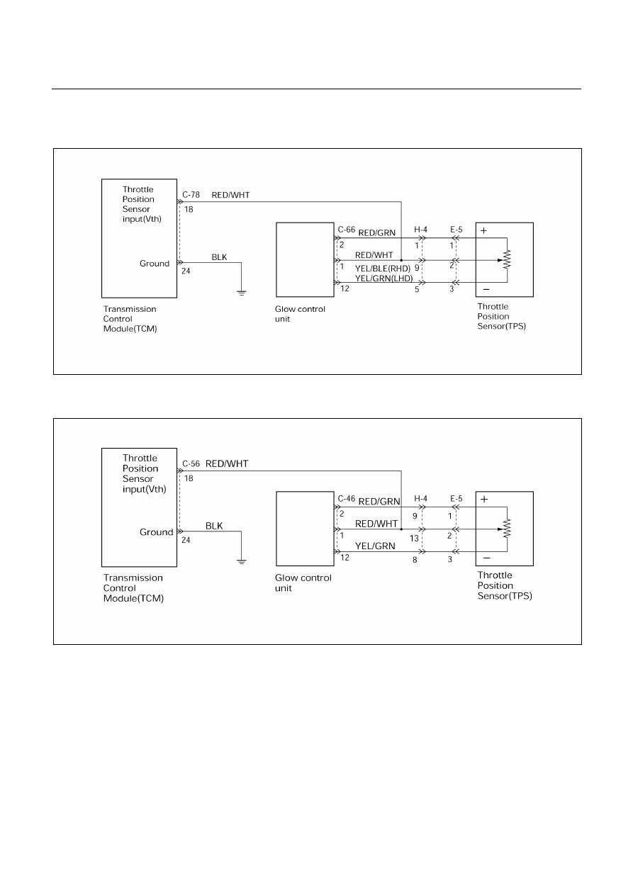
CODE 21 THROTTLE POSITION SENSOR (TPS) SIGNAL (OPEN/SHORTED
CIRCUIT)
UBS
D07R200024
TF
D07R200016

7A-30 AUTOMATIC TRANSMISSION (AW30-40LE)
Circuit Description:
When the signal of the engine throttle position sensor
is located on the injection pump is supplied to the
transmission TCM, the TCM judges the opening
condition of the throttle.
The shift point of the transmission is determined by this
opening condition of the throttle.
Test Description:
The following numbers correspond to the step numbers
on the diagnostic chart.
1. Check that the throttle input voltage is 0.24 to 1.30
V.
2. At this test, check that as the throttle opens, the
voltage goes up and that the voltage reaches 5.30
to 7.50 V at the full open status.
6. Check the power supply voltage (7.0 – 8.0 V) of the
throttle position sensor.
Diagnostic Aids:
An intermittent may be caused by a poor connection,
rubbed through wire insulation or a wire broken inside
the insulation. Inspect related harness connector for
backed out terminals, improper mating, broken locks,
improperly formed or damaged terminals, poor terminal
to wire connection and damaged harness.
CODE 21 THROTTLE POSITION SENSOR (TPS) SIGNAL (OPEN/SHORTED
CIRCUIT)
Step Action
Value(s)
Yes
No
1
1. With the engine “off”, turn the ignition “on”.
2. Connect a voltmeter between the TCM 26
pin connector terminal (18) and ground
terminal (24).
Is the voltage within the specified value?
0.24−1.30 V
Go to Step 2
Go to Step 3
2
Open the throttle fully.
Is the voltage within the specified value?
5.30−7.50 V
The problem is
intermittent.
Refer to
“Diagnostic
Aids” .
Go to Step 3
3
Measure the voltage between TPS 3 pin
connector terminal (2) and (3).
Is the voltage within the specified value?
0.24−1.30 V
Go to Step 4
Go to Step 6
4
Open the throttle fully.
Is the voltage within the specified value?
5.30−7.50 V
Go to Step 5
Go to Step 6
5
1. Check the wiring harness between the TCM
connector terminal (18) and TPS connector
terminal (2) or grow control unit 20 pin
connector terminal (1).
2. Or TCM is faulty.
Was a problem found and corrected?
−
Go to Step 9
−
6
1. Disconnect the TPS wiring harness
connector (H-4).
2. Connect a voltmeter between the connector
terminal (H4-1) and (H4-5)(UBS), or terminal
(H4-9) and (H4-8)(TF).
Is the voltage within the specified value?
7.25−7.55V
Go to Step 7
Go to Step 8
7
Check the TPS connector. If OK, replace TPS.
Is the replacement complete?
−
Go to Step 9
−
8
Check the wiring harness between the TPS and
grow control unit. If OK, replace the grow control
unit.
Is the replacement complete?
−
Go to Step 9
−
9
1. After the repair is complete, use the scan
tool to select “DTC”, then “Clear Info”
function.
2. Make a road running test for the vehicle.
3. Review the scan tool “DTC Info”.
Has the last test failed or is the current DTC
displayed?
−
Begin the
diagnosis
again
Go to Step 1
System OK
AUTOMATIC TRANSMISSION (AW30-40LE) 7A-31
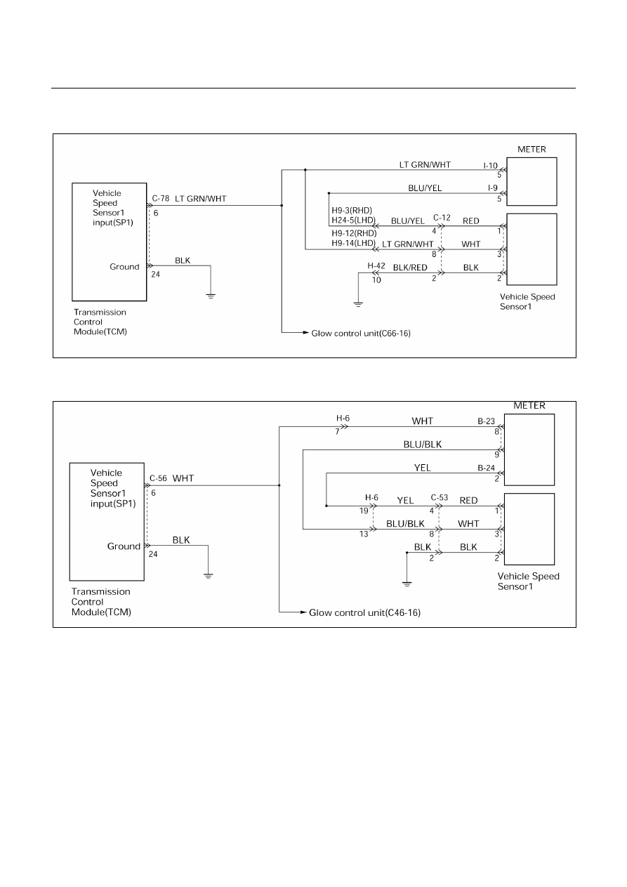
CODE 24 VEHICLE SPEED SENSOR 1 (OPEN/SHORTED CIRCUIT)
UBS
D07R200025
TF
D07R200017
Circuit Description:
Speed information is provided by the vehicle speed
sensor 1 to the meter.
In the meter, the pulses of the speed sensor are
converted to speed signals (pulses), and these signals
are output to the TCM. The TCM converts these pulse
voltages to km/h signals.
Test Description:
The following numbers correspond to the step numbers
on the diagnostic chart.
2. The cause of code 24 setting is due to the
operation fault of the speedometer.
3. Speed signals are output from the meter. The
sensor power supply is given from the TCM.
Diagnostic Aids:
An intermittent may be caused by a poor connection,
rubbed through wire insulation or a wire broken inside
the insulation. Inspect related harness connector for
backed out terminals, improper mating, broken locks,
improperly formed or damaged terminals, poor terminal
to wire connection and damaged harness.
Нет комментариевНе стесняйтесь поделиться с нами вашим ценным мнением.
Текст