Isuzu D-Max / Isuzu Rodeo (TFR/TFS). Manual — part 1791
UNIT REPAIR (JR405E) 7A4-31
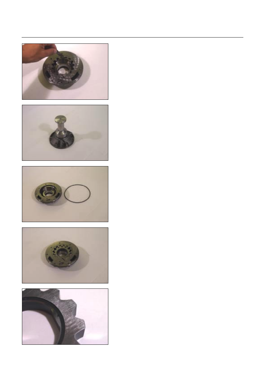
13PUMP46
Outer rotor
•
Install the outer rotor to the oil pump housing.
•
Measure the gap between the outer rotor and the
crescent.
If the measured gap is outside the specified range, the
outer rotor must be replaced.
Outer rotor and crescent gap:
0.02~0.15 mm (0.0008~0.0059 in)
14PUMP28
Reassembly steps
Coat the parts with ATF before installing them.
1. Oil seal
•
Use the oil seal installer to install new oil seal to the oil
pump housing.
Oil seal installer: 5-8840-2761-0
15PUMP18
2. O-ring (small)
Install new O-ring (small) to the oil pump housing.
16PUMP29
3. Outer rotor
4. Inner rotor
Install the outer rotor and the inner rotor to the oil pump
housing.
17PUMP42
NOTE:
The identification mark on the inner rotor must be facing
the inside of the oil pump housing.

7A4-32 UNIT REPAIR (JR405E)
18PUMP07
5. Oil pump cover
6. Oil pump housing
Install the oil pump cover to the oil pump housing.
Tighten the 8 bolts to the specified torque.
Torque: 9 N
⋅⋅⋅⋅
m (78 Ib
⋅⋅⋅⋅
in)
7. O-ring (large)
Install the O-ring (large) to the oil pump cover.
8. Seal ring
Install the 4 seal rings to the oil pump cover.
UNIT REPAIR (JR405E) 7A4-33
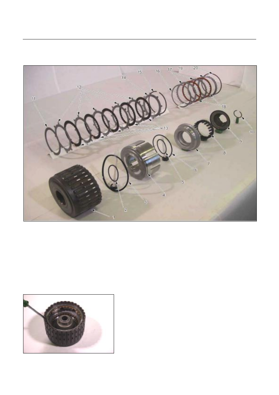
CLUTCH PACK (REVERSE AND
HIGH CLUTCH ASSEMBLY)
01R&H17
Legend
1. Reverse and high clutch drum
2. Seal ring (reverse clutch)
3. Lip seal (reverse clutch)
4. Reverse clutch piston
5. Seal ring (small, high clutch)
6. Seal ring (large, high clutch)
7. High clutch piston
8. Return spring
9. High clutch cover
10. Snap ring
11. Dish plate (high clutch)
12. Driven plates (5, high clutch)
13. Drive plates (5, high clutch)
14. Retaining plate (high clutch)
15. Snap ring (high clutch)
16. Dish plate (reverse clutch)
17. Driven plates (2, reverse clutch)
18. Drive plates (2, reverse clutch)
19. Retaining plate (reverse clutch)
20. Snap ring (reverse clutch)
02R&H18
Disassembly steps
1. Snap ring
Remove the reverse clutch snap ring.
7A4-34 UNIT REPAIR (JR405E)
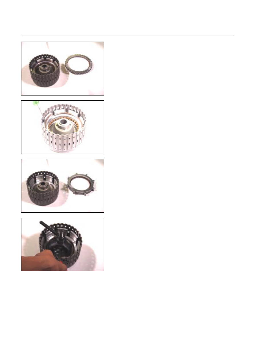
03R&H21
2. Retaining plate, drive plate, driven plate and dish plate
Remove the reverse clutch retaining plate, the 2 drive
plates, the 2 driven plates, and the dish plate.
04R&H22
3. Snap ring
Remove the high clutch snap ring.
05R&H25
4. Retaining plate, drive plate, driven plate and dish plate
Remove the high clutch retaining plate, the 5 drive plates,
the 5 driven plates, and the dish plate.
07R&H28
5. Snap ring
6. High clutch cover
7. Return spring
•
Install the spring compressor to the reverse and high
clutch drum.
Spring compressor: 5-8840-2767-0
•
Carefully press the high clutch cover down .
Take care not to damage the return spring.
•
Remove the snap ring.
•
Remove the high clutch cover and the return spring.
Нет комментариевНе стесняйтесь поделиться с нами вашим ценным мнением.
Текст