Isuzu D-Max / Isuzu Rodeo (TFR/TFS). Manual — part 92

4JA1-TC/4JH1-TC ENGINE DRIVEABILITY AND EMISSIONS
6E–363
LACK OF POWER, SLUGGISH OR SPONGY SYMPTOM
DEFINITIONS: Engine delivers less than expected power. Attempting part-throttle acceleration results in little or no
increase in vehicle speed.
Step
Action
Value(s)
Yes
No
1
Was the “On-Board Diagnostic (OBD) System Check”
performed?
—
Go to Step 2
Go to On Board
Diagnostic
(OBD) System
Check
2
1. Perform a bulletin search.
2. If a bulletin that addresses the symptom is found,
correct the condition as instructed in the bulletin.
Was a bulletin found that addresses the symptom?
—
Verify repair
Go to Step 3
3
Was a visually/physical check performed?
—
Go to Step 4
Go to Visual /
physical Check
4
Is the customer using the incorrect fuel type?
Diesel fuel
only
Replace with
diesel fuel
Go to Step 5
5
Visually/physically inspect for the following conditions.
• Restrict air intake system. Check for a restricted air
filter element, or foreign objects blocking the air
intake system
• Check for objects blocking or excessive deposits in
the throttle bore and on the throttle plate
• Check for a condition that causes a large vacuum
leak, such as an incorrectly installed or faulty
crankcase ventilation hose.
• Restrict air intake system at the turbocharger.
Check for objects blocking the turbocharger
compressor wheel or turbine shaft sticking.
If a problem is found, repair as necessary.
Was a problem found?
—
Verify repair
Go to Step 6
6
Check the ECM & PSG grounds to verify that they are
clean and tight. Refer to the ECM wiring diagrams.
Was a problem found?
—
Verify repair
Go to Step 7
7
1. Using the Tech 2, display the ECT sensor and IAT
sensor value.
2. Check the displayed value.
Does the Tech 2 indicate correct temperature
depending on engine condition?
If a problem is found, repair as necessary.
Was the problem found?
—
Verify repair
Go to Step 8
8
1. Using the Tech 2, display the FT sensor value.
2. Check the displayed value.
Does the Tech 2 indicate correct temperature
depending on engine condition?
If a problem is found, repair as necessary.
Was the problem found?
—
Go to Step 30
Go to Step 9
9
1. Using the Tech 2, ignition “On” and engine “Run”.
2. Monitor the “Mass Air Flow” in the data display.
Does the Tech 2 indicate correct “Mass Air Flow”
depending on accelerator pedal operation?
—
Go to Step 14
Go to Step 10

6E–364
4JA1-TC/4JH1-TC ENGINE DRIVEABILITY AND EMISSIONS
10
Remove the MAF & IAT sensor assembly and check
for the following conditions.
• Objects blocking at the MAF sensor element.
If a problem is found, repair as necessary.
Was the problem found?
—
Verify repair
Go to Step 11
11
Check the MAF sensor harness for the following
conditions.
• Check for poor connector connection.
• Check for misrouted harness.
• Check for any accessory parts which may cause
electric interference.
If a problem is found, repair as necessary.
Was a problem found?
—
Verify repair
Go to Step 12
12
Substitute a known good MAF & IAT sensor assembly
and recheck.
Was the problem solved?
—
Go to Step 13
Go to Step 30
13
Replace the MAF & IAT sensor assembly.
Is the action complete?
—
Verify repair
—
14
1. Using the Tech 2, ignition “On” and engine “Off”.
2. Monitor the “Pedal/Throttle Position” and “Idle
Switch” in the data display.
Does the Tech 2 indicate correct “Pedal/Throttle
Position” from 0% to 100% and correct “Idle Switch”
status depending on accelerator pedal operation?
—
Go to Step 19
Go to Step 15
15
1. Using the Tech 2, ignition “On” and engine “Off”.
2. Monitor the “Pedal/Throttle Position” and “Idle
Switch” in the data display.
3. Adjust the accelerator cable or TPS within 0% to
100%.
Was the problem solved?
—
Verify repair
Go to Step 16
16
Check the TPS harness for the following conditions.
• Check for poor connector connection.
• Check for misrouted harness.
• Check for any accessory parts which may cause
electric interference.
If a problem is found, repair as necessary.
Was a problem found?
—
Verify repair
Go to Step 17
17
Substitute a known good TPS and recheck.
Was the problem solved?
—
Go to Step 18
Go to Step 30
18
Replace the TPS.
Is the action complete?
—
Verify repair
—
Step
Action
Value(s)
Yes
No

4JA1-TC/4JH1-TC ENGINE DRIVEABILITY AND EMISSIONS
6E–365
19
1. Using the Tech 2 and ignition “On” and engine
“Run”.
2. Monitor the following parameters in the data
display.
• “Desired Injection Quantity” & “Injection Quantity”
• “Desired Injection Start” & “Actual Injection Start”
Are the large gap or unstable parameter displayed
between “Desired” and “Actual”?
—
Go to Step 23
Go to Step 20
20
Using the vacuum pump and check the EGR valve (if
equipped) operation for the following condition through
the small window.
• Restrict shaft movement. Check for objects sticking
the shaft, broken diaphragm or excessive carbon
deposit.
If a problem is found, repair as necessary.
Was a problem found?
—
Verify repair
Go to Step 21
21
Using the vacuum pump and check the exhaust
throttle valve (if equipped) operation for the following
condition.
• Restrict shaft movement. Check for objects sticking
the shaft, broken diaphragm or excessive carbon
deposit.
Was a problem found?
—
Verify repair
Go to Step 22
Step
Action
Value(s)
Yes
No
When idling or part-throttle When accelerated
High
Desired
Low
Time
Actual
High
Low
Desired
Actual
Time
Vacuum Pump
Small Window
6E–366
4JA1-TC/4JH1-TC ENGINE DRIVEABILITY AND EMISSIONS
22
Check the exhaust system for a possible restriction.
• Damaged or collapsed pipes or catalytic converter.
• Internal muffler failure.
If a problem is found, repair as necessary.
Was a problem found?
—
Verify repair
Go to Step 23
23
Visually/physically inspect for the following conditions.
• Restrict fuel supply system. Check for a pinched
fuel hose/pipe.
• Check for a condition that causes fuel waxing or
icing, such as the customer is using an incorrect
fuel type in winter season or water mixed with the
fuel.
If a problem is found, repair as necessary.
Was a problem found?
—
Verify repair
Go to Step 24
24
Replace the fuel filter.
Was the problem solved?
—
Verify repair
Go to Step 25
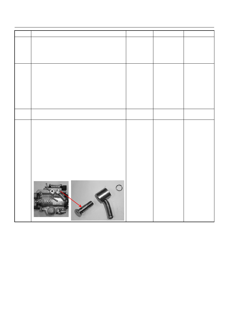
25
Remove the eye bolt with gauze filter from the
injection pump and check for the following conditions.
• Objects blocking at the gauze filter. Check for a
condition that causes contaminated fuel, such as
the customer is using an aftermarket fuel filter or
extended maintenance interval.
• Check for a condition that causes fuel waxing or
icing, such as the customer is using an incorrect
fuel type in winter season or water mixed with the
fuel.
If a problem is found, repair as necessary.
Was the problem found?
—
Replace the eye
bolt with gauze
filter and verify
repair
Go to Step 26
Step
Action
Value(s)
Yes
No
Нет комментариевНе стесняйтесь поделиться с нами вашим ценным мнением.
Текст