Isuzu D-Max / Isuzu Rodeo (TFR/TFS). Manual — part 1973
4C2-12 FRONT DRIVING AXLE
DISASSEMBLY
WARNING:
DURING THE WORK, BE SURE THAT THE DIFF CASE IS
SUPPORTED BY THE JACK.
Preparations:
• Jack up the vehicle and support it using jack stands.
• Remove the tire and wheel.
• Remove the drain bolt to drain differential oil.
• Remove the brake caliper fixing bolt and hang the caliper.
Refer to Section 5A2 "HYDRAULIC FOUNDATION
BRAKES".
1. Hub Assembly (Disc, Back Plate and Knuckle)
• Remove the locking hub. Refer to this Section "FRONT
HUB AND DISC".
• Disconnect the knuckle and the suspension arm. Refer to
Section 3C "FRONT SUSPENSION".
2. Steering Link and Arm Assembly
Refer to Section 3B3 "STEERING LINKAGE".
3. Suspension Crossmember
4. Propeller Shaft
Refer to Section 4A "PROPELLER SHAFT".
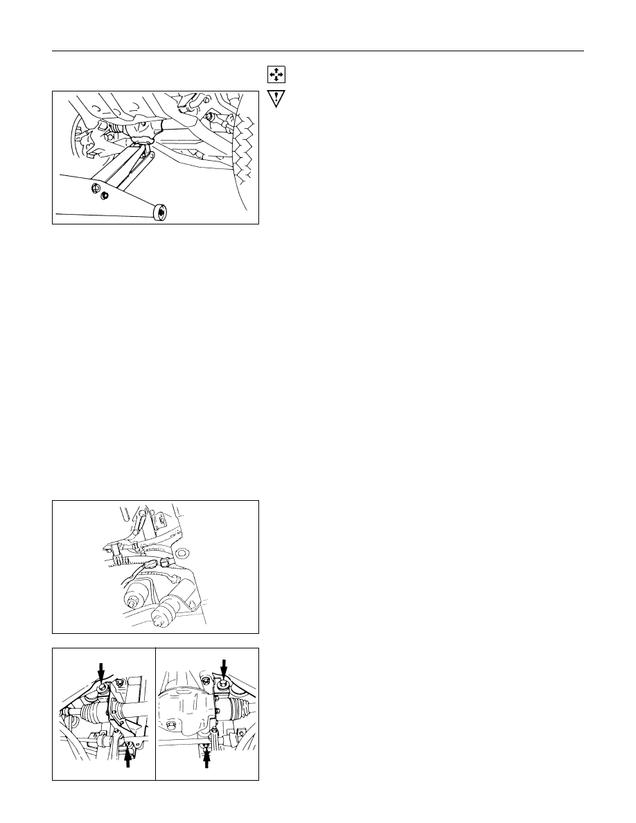
5. Protector (w/shift on the fly system)
6. Breater Hose
• Disconnect breather hose from front drive axle.
7. Connector (w/shift on the fly system)
• Disconnect actuator connector.
• Disconnect shift detective switch connector.
8. Mounting Bolt and Nut
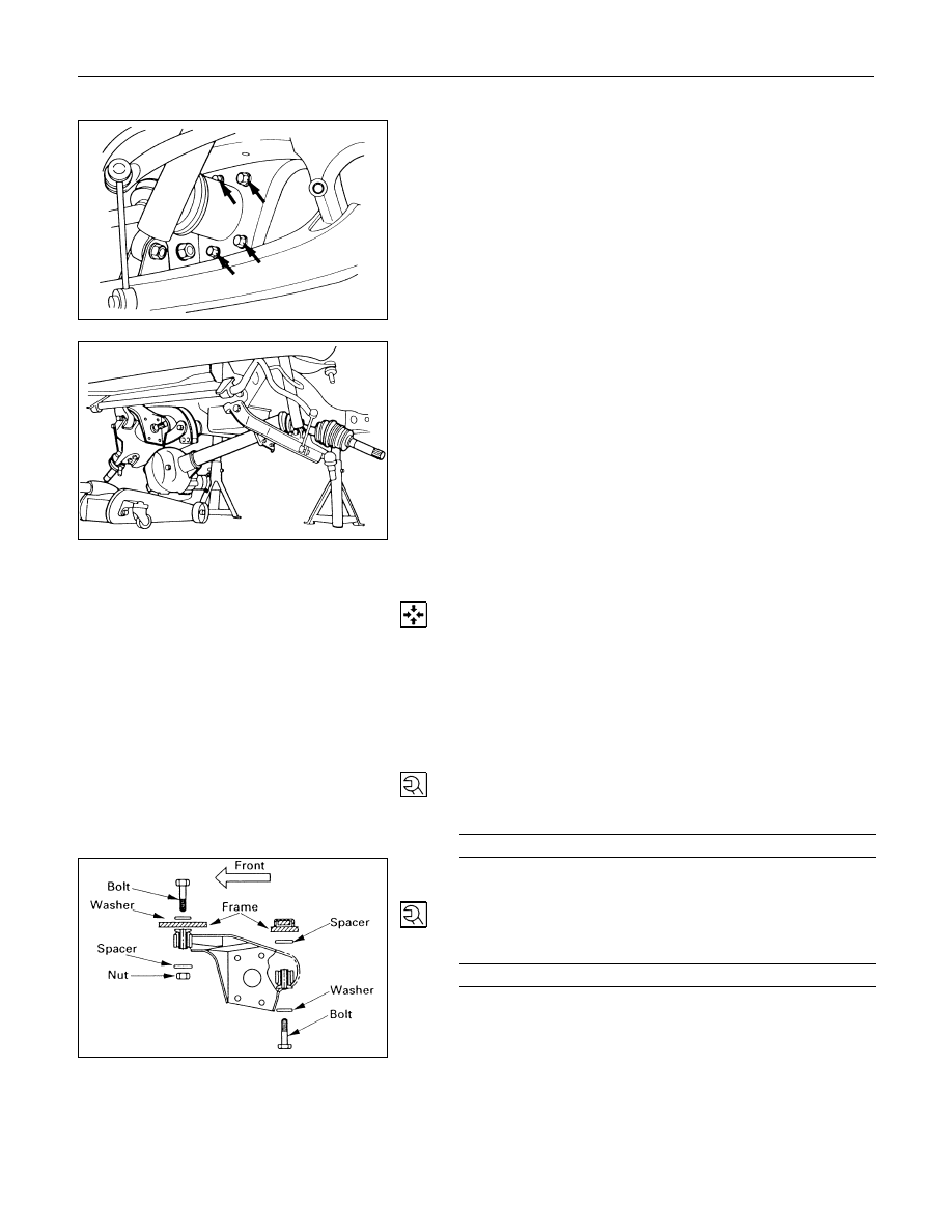
FRONT DRIVING AXLE 4C2-13
9. Washer and Spacer
10.Bolt
Remove the mounting bracket fixing bolt.
11.Front Axle Case Assembly and Front Drive Shaft
Assembly (LH side).
Lower the vehicle and disconnect the RH front drive shaft
assembly, and then remove the front axle case assembly
and front drive shaft assembly (LH).
12.Front Drive Shaft Assembly (RH side)
REASSEMBLY
12.Front Drive Shaft Assembly (RH side)
Lay the assembly on the lower arm.
11.Front Axle Case Assembly and Front Drive Shaft
Assembly (LH side)
Place the axle case on the jack, connect to the front drive
shaft assembly (RH) before installing to the vehicle.
10.Bolt
Tighten the mounting bracket fixing bolt to the specified
torque.
Mounting Bracket Fixing Bolt Torque
N
⋅m (kg⋅m/lb⋅ft)
116 (11.8/85)
9. Washer and Spacer
8. Mounting Bolt and Nut
Tighten the mounting bolt and nut to the specified torque.
Front Drive Axle Case Mounting
Bolt and Nut Torque
N
⋅m (kg⋅m/lb⋅ft)
152 (15.5/112)

4C2-14 FRONT DRIVING AXLE
7. Connector (W/Shift on the fly system)
Fit actuator connector.
6. Breather Hose
NOTE:
Be careful not to permit the entry of dust into the hose and
connector.
5. Protector (w/shift on the fly system)
Tighten bolts to specified torque.
Bolt Torque
N
⋅m (kg⋅m/lb⋅ft)
26 (2.7/20)
4. Propeller Shaft
Refer to Section 4A "FRONT PROPELLER SHAFT".
3. Suspension Crossmember
2. Steering Link and Arm Assembly
Refer to Section 3B3 "STEERING LINKAGE".
1. Hub Assembly (Disc, Back Plate and Knuckle)
Refer to Section 5A2 "HYDRAULIC FOUNDATION
BRAKES" and Section 3C "FRONT SUSPENSION".
FRONT DRIVING AXLE 4C2-15
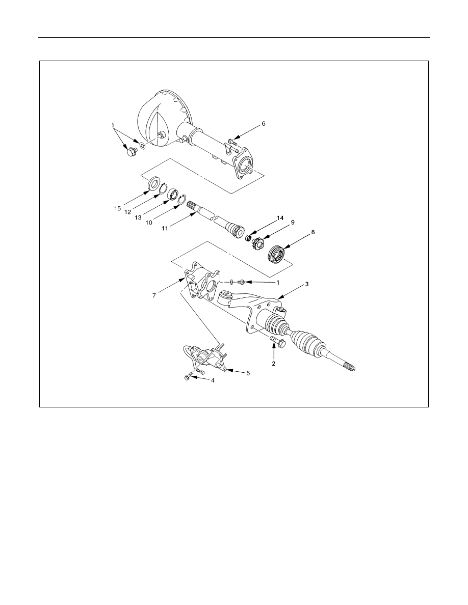
SHIFT ON THE FLY SYSTEM
Disassembly steps
1. Filler plug
2. Bolt
3. Front axle drive shaft (LH side)
4. Bolt
5. Actuator assembly
6. Bolt
7. Housing
8. Sleeve
9. Clutch gear
10.Snap ring
11.Inner shaft
12.Snap ring
13.Inner shaft bearing
14.Needle bearing
15.Oil seal
Reassembly steps
To reassemble, follow the disassembly steps in
the reverse order.
Нет комментариевНе стесняйтесь поделиться с нами вашим ценным мнением.
Текст