Isuzu D-Max / Isuzu Rodeo (TFR/TFS). Manual — part 1516
8-164 ELECTRICAL-BODY AND CHASSIS
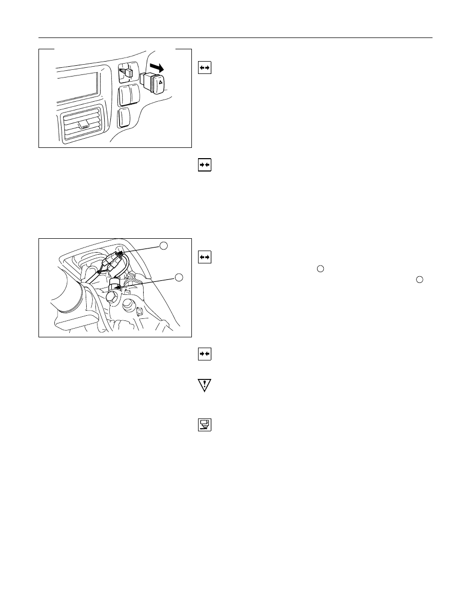
HAZARD WARNING FLASHER SWITCH
Removal
1. Instrument Panel Cluster Assembly
• Refer to Section 10 “BODY” for instrument panel cluster
assembly removal steps.
2. Hazard Warning Switch
• Disconnect the switch connector.
• To remove the switch, push the lock from the back side
of the cluster assembly.
Installation
To install, follow the removal procedure in the reverse order.
Connector
Be absolutely sure that the hazard warning flasher switch
connector is securely connected.
This will prevent a poor contact and an open circuit.
1
2
BACK UP LIGHT SWITCH
Removal
1. Disconnect the connector
1
.
2. Remove the back up light switch from the transmission
2
.
Installation
Follow the removal procedure in the reverse order to install the
back up light switch.
Pay close attention to the important points mentioned in the
following paragraphs.
Back up Light Switch Threads
Apply liquid gasket to the threaded portion and install the back
up light switch.
Connector
Be absolutely sure that the back up light connector is securely
connected.
This will prevent a poor contact and an open circuit.
ELECTRICAL-BODY AND CHASSIS 8-165
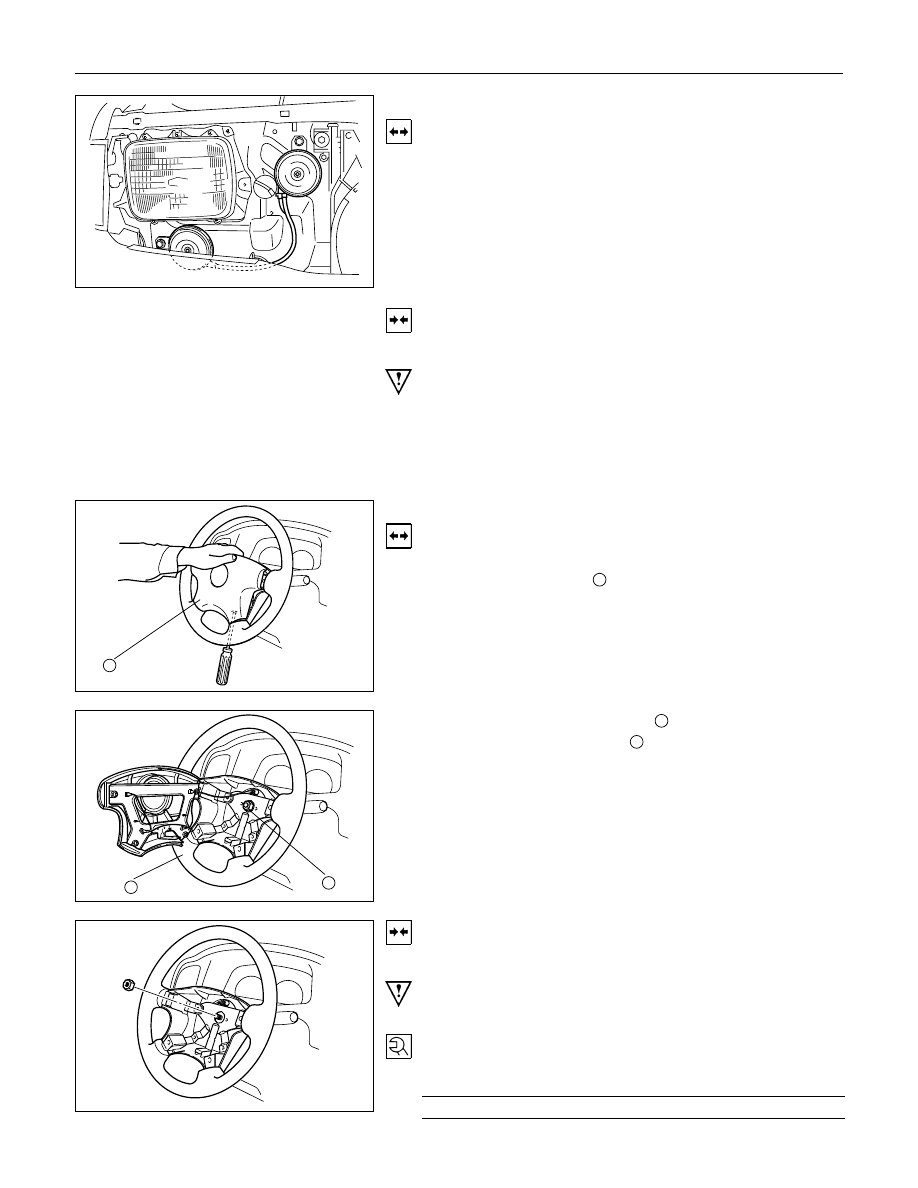
HORN
Removal
1. Remove the radiator grille.
Refer to the “HEADLIGHT” removal procedure.
2. Loosen the horn bolt.
3. Disconnect the horn connector.
Installation
Follow the removal procedure in the reverse order to install the
horn.
Pay close attention to the important point mentioned in the
following paragraphs.
Connector
Be absolutely sure the horn connector is securely connected.
This will prevent a poor contact and open circuit.
1
HORN SWITCH
Removal
1. Remove the screws on the lower part of the steering wheel.
2. Remove the horn pad
1
.
3. Remove the horn wiring connector.
3
2
4. Remove the steering wheel nut
2
.
5. Remove the steering wheel
3
.
6. Remove the connector.
7. Remove the horn switch (combination switch).
Installation
Follow the removal procedure in the reverse order to install the
horn switch.
Pay close attention to the important points mentioned in the
following paragraphs.
Steering Wheel Nut
Tighten the nut to the specified torque.
Steering Wheel Nut Torque
N
⋅m (kgf⋅m/lb⋅ft)
34.3
±4.9 (3.5±0.5 / 25±3.6)
8-166 ELECTRICAL-BODY AND CHASSIS
INSPECTION AND REPAIR
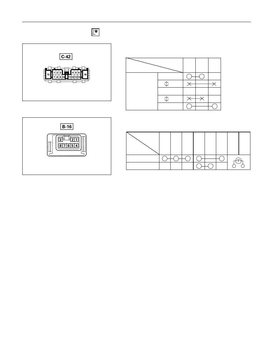
Switch side
TURN SIGNAL SWITCH
Lighting Switch Connections
Terminal No.
SW position
3
4
5
Left
Neutral
Right
Turning
direction
Switch side
HAZARD WARNING FLASHER SWITCH
Hazard Warning Flasher Switch Connections
Terminal
No.
SW position
4
5
6
7
8
2
1
3
ON
OFF
ELECTRICAL-BODY AND CHASSIS 8-167
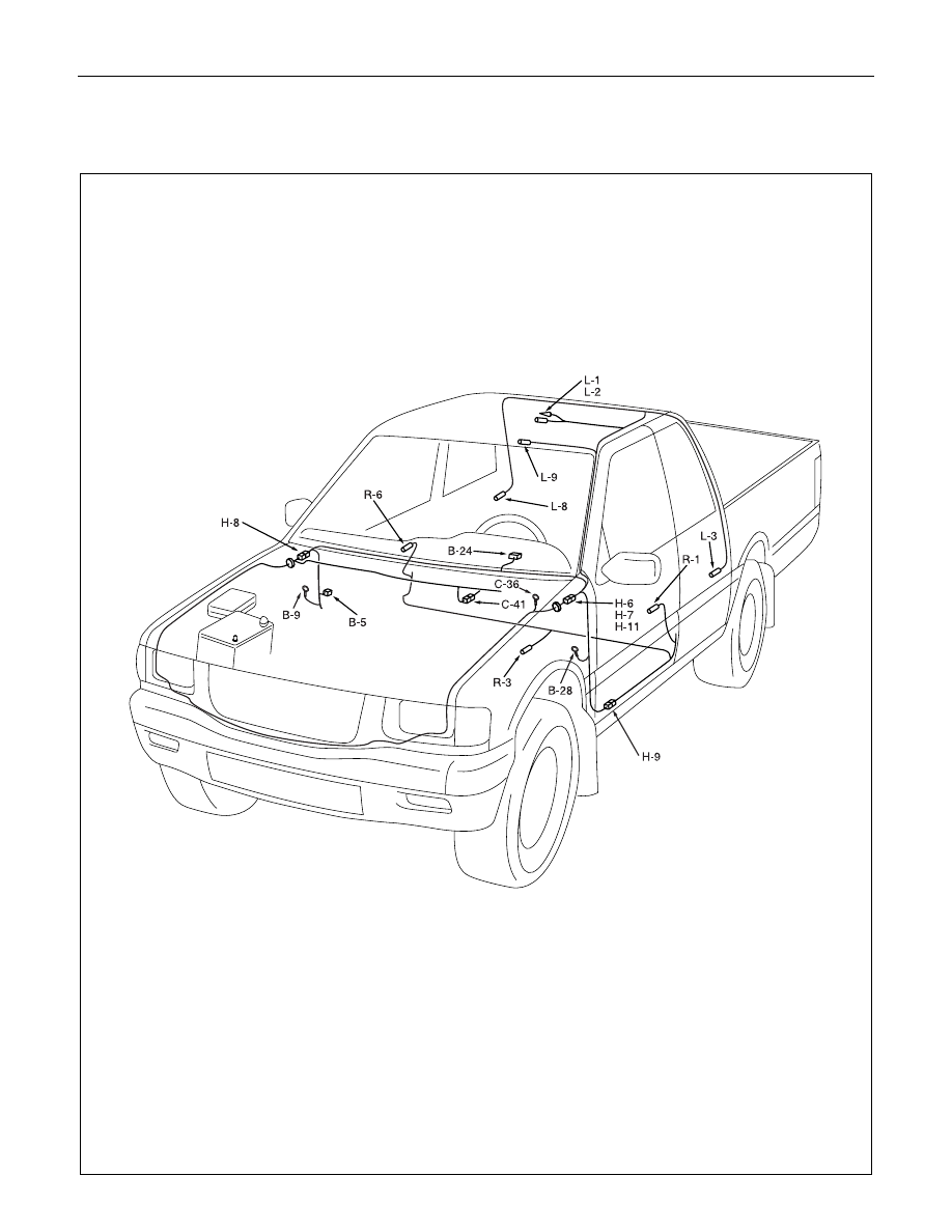
DOME LIGHT, SPOT LIGHT AND WARNING BUZZER
PARTS LOCATION (LHD)
Нет комментариевНе стесняйтесь поделиться с нами вашим ценным мнением.
Текст