Isuzu D-Max / Isuzu Rodeo (TFR/TFS). Manual — part 1124
ELECTRICAL-BODY AND CHASSIS 8-253
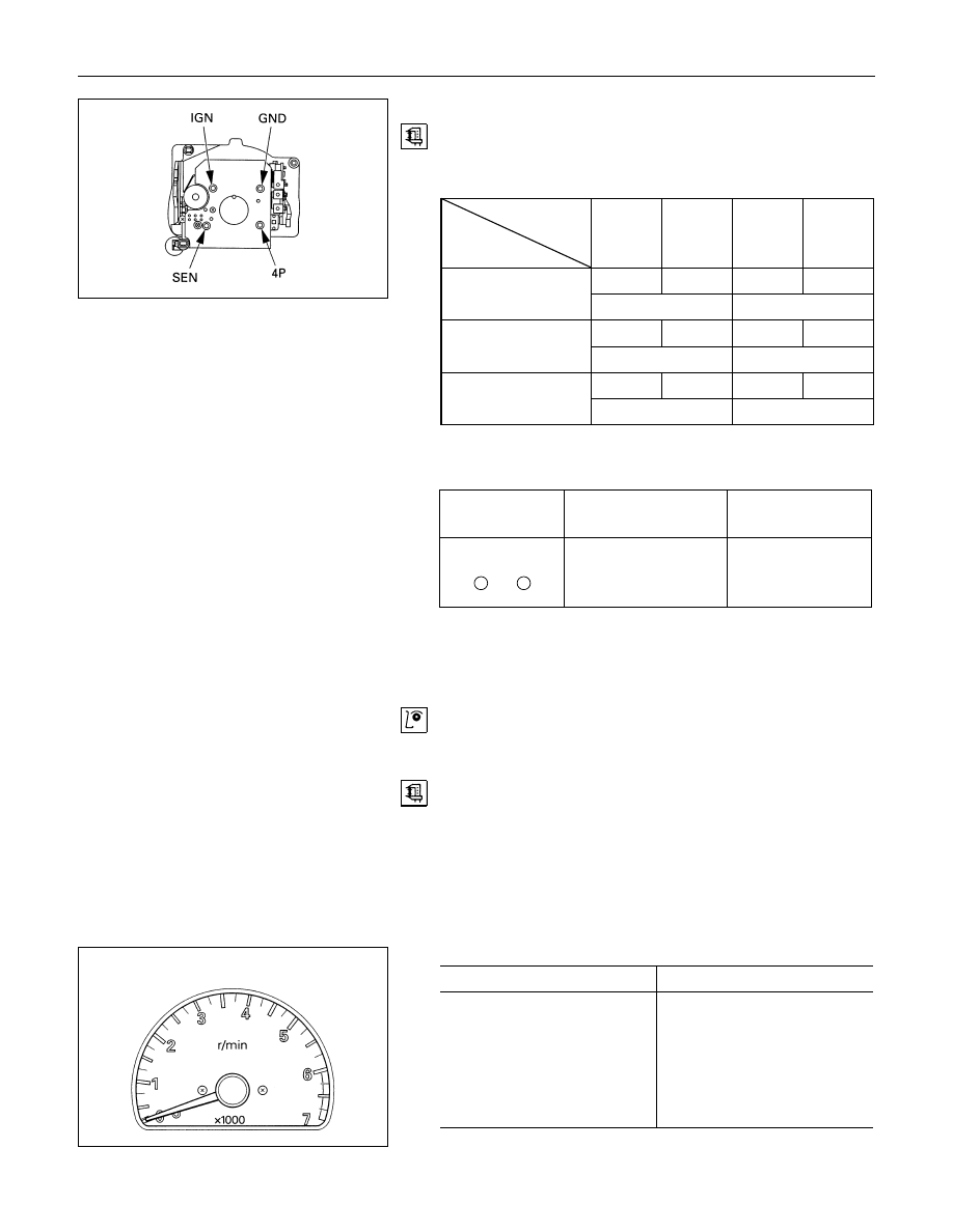
Speedometer Off-Vehicle Inspection
Remove the speedometer from the meter assembly and
measure the resistance and the current consumption between
each terminal.
Speedometer Resistance
Tester
Terminal
terminal
symbol
Red (+)
Black (-) Black (-)
Red (+)
IGN
GND
IGN
GND
∞
30.6 - 37.4k
SEN
GND
SEN
GND
28.8 - 35.2k
∞
4P
GND
4P
GND
13.5 - 16.5k
∞
4P - GND
SEN - GND
IGN - GND
Note: Use the analog type circuit tester (range:
× 1k).
Speedometer Current Consumption
Terminal
symbol
Current
consumption
Remarks
IGN - GND
+
-
85
± 15mA
(when 12
± 1V
applied)
No signal input
Note: 1. Use the analog type circuit tester.
2. Since the current consumption fluctuates when the
source voltage varies, check to be sure that the
voltage applied is 12V
± 1V.
Tachometer On-Vehicle Inspection
1. Attach a tune-up tester to the engine.
2. Start the engine.
3. Compare the tachometer reading and the tester reading.
If the tachometer indication is outside the permissible
range, the tachometer must be replaced.
4. Gradually increase and decrease the engine speed.
Note the movement of the tachometer needle.
If the needle movement is sluggish, the tachometer must be
replaced.
Gasoline engine
rpm
Indication
Permissible Range
1,000
940-1060
2,000
1875-2125
3,000
2850-3150
4,000
3820-4180
5,000
4820-5180
6,000
5820-6180
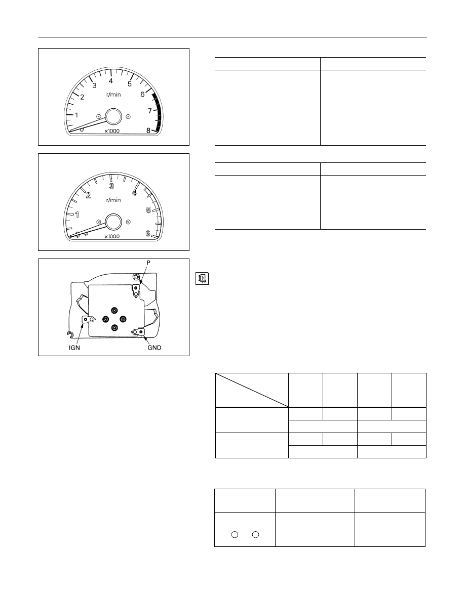
8-254 ELECTRICAL-BODY AND CHASSIS
Gasoline engine (6VD1)
Gasoline engine (6VD1)
rpm
Indication
Permissible Range
1,000
900-1060
2,000
1820-2070
3,000
2820-3120
4,000
3820-4180
5,000
4820-5180
6,000
5820-6180
7,000
6820-7180
Diesel engine
Diesel engine
rpm
Indication
Permissible Range
750
690-810
2,000
1875-2125
3,000
2850-3150
4,000
3820-4180
5,000
4820-5180
Tachometer Off-Vehicle Inspection
Remove the tachometer from the meter assembly and
measure the resistance value and the current consumption
between each terminal.
Tachometer Resistance
Tester
Terminal
terminal
symbol
Red (+)
Black (-) Black (-)
Red (+)
IGN
GND
IGN
GND
∞
23 - 31k
P
GND
P
GND
28.8 - 35.2k
∞
P - GND
IGN - GND
Note: Use the analog type circuit tester (range:
× 1k).
Tachometer Current Consumption
Terminal
symbol
Current
consumption
Remarks
IGN - GND
+
-
90
± 15mA
(12
± 1V when
voltage applied)
No signal input
Note: 1. Use the analog type circuit tester.
2.
Since the current consumption fluctuates as the
source voltage varies, check to be sure that the
voltage applied is 12V
± 1V.
ELECTRICAL-BODY AND CHASSIS 8-255
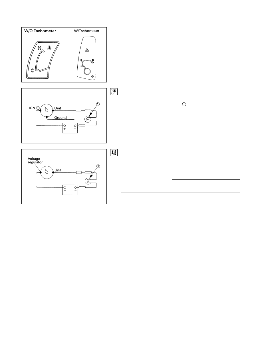
TEMPERATURE GAUGE AND THERMO
UNIT
Temperature Gauge On-Vehicle Inspection
1. Disconnect the temperature gauge wire connector.
2. Connect a 3.4 Watt test bulb
1
to the ground.
The gauge needle should move the middle part of the
gauge
Temperature Gauge Off-Vehicle Inspection
Use a circuit tester to measure the temperature gauge
resistance.
Temperature Gauge Resistance
Ω
Standard
Measuring Point
With
Tachometer
Without
Tachometer
IGN (+) - Ground
130
-
IGN (+) - UNIT
82
-
UNIT - Ground
212
-
VOLTAGE
REGULATOR - UNIT
-
25

8-256 ELECTRICAL-BODY AND CHASSIS
Thermo Unit Inspection
The thermo unit is thermistor type and must be inspected
under the conditions as shown in the left chart.
1. Put the deviation of the galvanometer to 0 by using the
variable resistor, switch the thermo unit off and then
measure the resistance of the resistor through the bridge.
Confirm that the resistance is continuously variable in any
other points than those shown in the following table.
2. Dip the thermo unit into 80 - 90
°C (176 - 194°F) water and
confirm that there is no bubble continuously coming out of
inside of the unit.
Replace the unit when the result of inspection is found
abnormal.
Temperature
Check
condition
50
°C
(122
°F)
115
°C
(239
°F)
7V 55
Ω
Gauge
Resistance
+33.6
226.0
-36.6
+1.71
26.4
-2.21
7V 25
Ω
Gauge
value (
Ω)
-
+2.68
24.3
-3.68
Нет комментариевНе стесняйтесь поделиться с нами вашим ценным мнением.
Текст