Isuzu D-Max / Isuzu Rodeo (TFR/TFS). Manual — part 228
ENGINE DRIVEABILITY AND EMISSIONS
6E–153
6
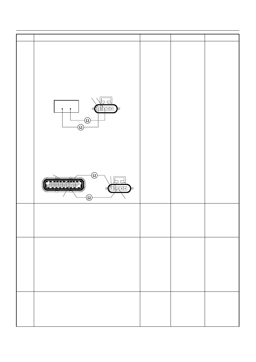
Using the DVM and check the O
2
sensor circuit.
Breaker box is available:
1. Ignition “Off”, engine “Off”.
2. Install the breaker box as type A. (ECM
disconnected) Ref. 6E-80.
3. Disconnect the O
2
sensor.
4. Check the circuit for open circuit.
Was the problem found?
Breaker box is not available:
1. Ignition “Off”, engine “Off”.
2. Disconnect the O
2
sensor connector and ECM
connector.
3. Check the circuit for open circuit.
Was the problem found?
—
Repair faulty
harness and
verify repair
Go to Step 13
7
1. Using the Tech 2, ignition “On” and engine “On”.
2. Monitor the “Manifold Absolute Pressure” in the
data display.
Does the Tech 2 indicate correct “Manifold Absolute
Pressure” in accordance with engine speed or
acceleration?
—
Go to Step 9
Go to Step 8
8
Remove the MAP sensor and check for the following
conditions.
• Objects blocking the air cleaner.
• Objects blocking the MAP sensor.
• Objects blocking the throttle valve.
• Vacuum leaking at intake duct.
• Vacuum leaking at throttle body.
If a problem is found, repair as necessary.
Was the problem found?
—
Verify repair
Go to Step 9
9
1. Using the Tech 2, ignition “On” and engine “On”.
2. Select the “Miscellaneous Test” and perform the
“IAC Control” in the “IAC System”.
3. Operate the Tech 2 in accordance with procedure.
Was the engine speed changed, when the IAC valve is
operating step by step?
—
Go to Step 11
Go to Step 10
Step
Action
Value(s)
Yes
No
1 2
38
53
E77
1
2
21
6
C56(J2)
E77

6E–154
ENGINE DRIVEABILITY AND EMISSIONS
10
Check for the following conditions.
• Objects blocking the IAC valve.
• Objects blocking the throttle valve.
• Vacuum leaking at throttle body.
If a problem is found, repair as necessary.
Was the problem found?
—
Verify repair
Go to Step 11
11
Check for injector for the affected bank.
Refer to “Injector Coil Test & Injector Balance Test
Procedure”.
Was the injector operation correct?
—
Go to Step 12
Refer to Injector
Coil Test &
Injector
Balance Test
Procedure
12
Check for fuel pressure.
Refer to “Fuel System Diagnosis”.
Was the fuel pressure correct?
—
Go to Step 13
Refer to Fuel
System
Diagnosis
13
Replace the O
2
sensor.
Was the problem solved?
—
Verify repair
Go to Step 14
14
Is the ECM programmed with the latest software
release?
If not, download the latest software to the ECM using
the “SPS (Service Programming System)”.
Was the problem solved?
—
Verify repair
Go to Step 15
15
Replace the ECM.
Is the action complete?
IMPORTANT: The replacement ECM must be
programmed. Refer to section of the Service
Programming System (SPS) in this manual.
Following ECM programming, the immobiliser system
(if equipped) must be linked to the ECM. Refer to
section 11 “Immobiliser System-ECM replacement” for
the ECM/Immobiliser linking procedure.
—
Verify repair
—
Step
Action
Value(s)
Yes
No
ENGINE DRIVEABILITY AND EMISSIONS
6E–155
DIAGNOSTIC TROUBLE CODE (DTC) P0135 O
2
SENSOR HEATER CIRCUIT
(BANK 1 SENSOR 1)
Condition for setting the DTC and action taken when the DTC sets
Circuit Description
Heated oxygen sensors are used to minimize the
amount of time required for “Closed Loop” fuel control
operation and to allow accurate catalyst monitoring. The
oxygen sensor heater greatly decreases the amount of
time required for fuel control sensors Bank 1 HO2S 1 1
to become active. Oxygen sensor heaters are required
by catalyst monitor sensors Bank 1 HO2S 2 to maintain
a sufficiently high temperature which allows accurate
exhaust oxygen content readings further from the
engine.
The engine control module (ECM) will run the heater
test only after a cold start (determined by engine
coolant and intake air temperature at the time of start-
up) and only once during an ignition cycle. When the
engine is started the ECM will monitor the HO2S
voltage. When the HO2S voltage indicates a sufficiently
active sensor, the ECM looks at how much time has
elapsed since start-up. If the ECM determines that too
much time was required for the Bank 1 HO2S 1 to
Code
Type
DTC Name
DTC Setting Condition
Fail-Safe (Back Up)
P0135
A
O
2
SensorHeater Circuit (Bank 1 Sen-
sor 1)
1. No DTC relating to MAP sensor and ECT
sensor.
2. Engine coolant temperature is more than
60°C.
3. Engine run time is longer than 20 seconds.
4. MAP sensor output is more than 70KPa.
5. O
2
sensor bank 1 heater current more than
10mA.
No fail-safe function.
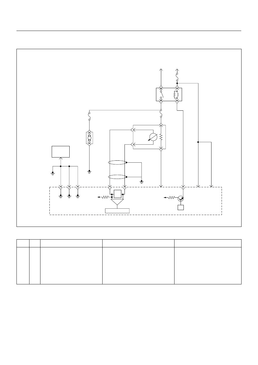
µP
V
Ign
-
+
Crankshaft
Position
Sensor
J1-1 J1-2 J1-17
Battery
Voltage
Battery
Voltage
2.0
WHT
ECM
10A
450
mV
A/D Converter
Vcc
+5V
-
+
TIMING
COVER
J2-6
J2-21
Fuel
Pump
FUEL
PUMP
20A
2.0
BLK
2.0
BLK/
BLU
Fuel
Pump
Relay
O
2
SENSOR
10A
Heated
O
2
Sensor
0.85
RED/
WHT
0.5
GRN/
WHT
0.5
RED/
WHT
0.5
BLU/
WHT
0.5
BLU
0.5 PNK
J2-31
J2-11
J2-2
J2-18
M
Engine
Control
Module
(ECM)
6E–156
ENGINE DRIVEABILITY AND EMISSIONS
become active, a Diagnostic Trouble Code P0135 will
set.
Diagnostic Aids
Check for the following conditions:
• Poor connection at ECM - Inspect harness
connectors for backed-out terminals, improper
mating, broken locks, improperly formed or damaged
terminals, and poor terminal-to-wire connection.
• Damaged harness - Inspect the wiring harness for
damage; shorts to ground, shorts to battery positive
and open circuits.
Diagnostic Trouble Code (DTC) P0135
O
2
Sensor Heater Circuit (Bank 1 Sensor 1)
Step
Action
Value(s)
Yes
No
1
Was the “On-Board Diagnostic (OBD) System Check”
performed?
—
Go to Step 2
Go to On Board
Diagnostic
(OBD) System
Check
2
1. Connect the Tech 2.
2. Review and record the failure information.
3. Select “F0: Read DTC Infor By Priority” in “F0:
Diagnostic Trouble Code”.
Is the DTC P0135 stored as “Present Failure”?
—
Go to Step 3
Refer to
Diagnostic Aids
and Go to Step
3
3
1. Using the Tech2, ignition “On” and engine “Off”.
2. Select “Clear DTC Information” with the Tech2 and
clear the DTC information.
3. Operate the vehicle and monitor the “F5: Failed
This Ignition” in “F2: DTC Information”.
Was the DTC P0135 stored in this ignition cycle?
—
Go to Step 4
Refer to
Diagnostic Aids
and Go to Step
4
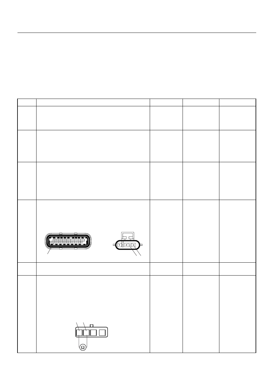
4
Check for poor/faulty connection at the O
2
sensor or
ECM connector. If a poor/faulty connection is found,
repair as necessary.
Was the problem found?
—
Verify repair
Go to Step 5
5
Visually check the O
2
sensor.
Was the problem found?
—
Go to Step 11
Go to Step 6
6
Using the DVM and check the O
2
sensor.
1. Ignition “Off”, engine “Off”.
2. Disconnect O
2
sensor connector
3. Measure the resistance of heater.
Was the tester indicated specified value?
Approximately
12.5
Ω at 20°C
Go to Step 7
Go to Step 11
3 4
31
C56(J2)
E77
3
4
1
2
3
4
O
2
Sensor
Нет комментариевНе стесняйтесь поделиться с нами вашим ценным мнением.
Текст