Isuzu D-Max / Isuzu Rodeo (TFR/TFS). Manual — part 573
6A – 130 ENGINE MECHANICAL
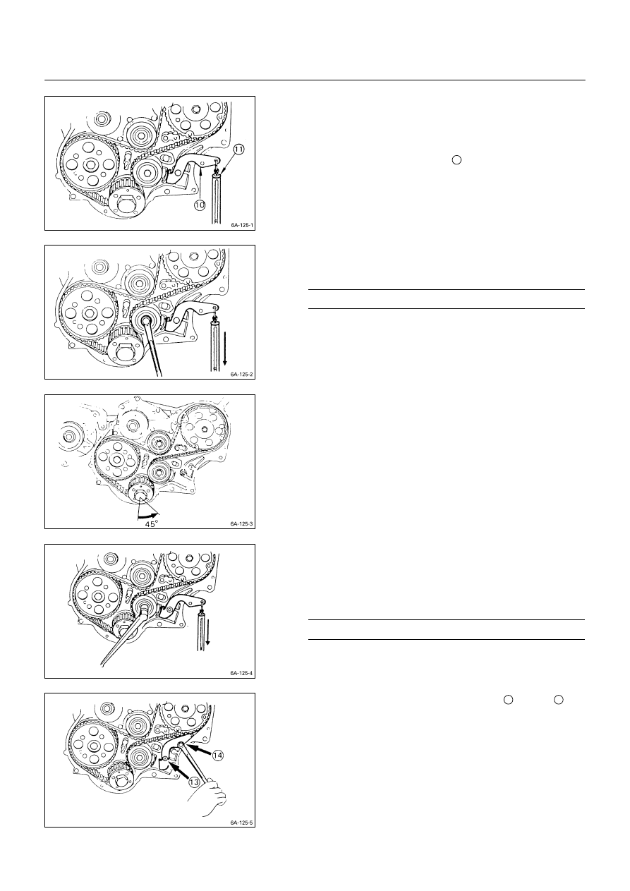
6) Set the tensioner adjusting lever
l
to the timing
pulley housing.
7) Remove the stopper bolts from the camshaft timing
pulley
c
and the injection pump timing pulley
d
.
8) Attach the spring balancer
11
.
9) Adjust timing belt tension by pulling straight down on
the spring balancer with the specified force.
Tension Adjusting Lever Force
kg (lb/N)
10 - 12 (22.1 – 26.5/98.1 – 117.7)
Note:
Timing belt tension must be adjusted.
Failure to adjust the timing belt tension will result in
timing belt damage.
10) Tighten the tension bolt.
11) Rotate the crankshaft 45 degrees counterclockwise.
Note:
Never rotate crankshaft clockwise when adjusting the
timing belt.
12) Readjust the timing belt tension.
Refer to Step 9
This will remove any remaining timing belt slack.
13) Tighten the tensioner bolt to the specified torque.
Tensioner Bolt Torque
kg·m (lb.ft/N·m)
7.7
±
1.0 (55.7
±
3.6/75.5
±
9.8)
14)Tighten the tension adjusting lever nut
13
and bolt
14
.
Note:
If on-vehicle timing belt replacement is performed, the
crankshaft must not be allowed to turn.
If the crankshaft is allowed to turn, piston and valve
damage will result.
ENGINE MECHANICAL 6A – 131
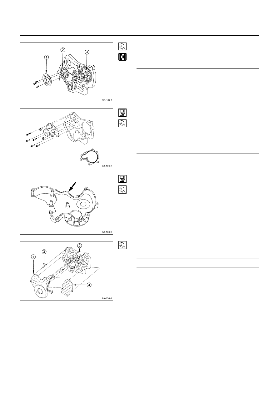
27. Camshaft Timing Pulley Flange
Tighten the timing pulley flange bolts to the specified
torque.
Timing Puley Flange Bolt Torque
kg·m (lb.ft/N·m)
1.9
±
0.5 (13.7
±
3.6/18.6
±
4.9)
28. Water Pump
1) Apply the recommended liquid gasket or its equivalent
to the water pump at the position shown in the
illustration.
Do not apply an excessive amount of liquid gasket.
2) Tighten the water pump bolts to the specified torque.
Water Pump Bolt Torque
kg·m (lb.ft/N·m)
2.0
±
0.5 (14.5
±
3.6/19.6
±
4.9)
29. Timing Pulley Housing Lower Cover
30. Timing Pulley Housing Upper Cover
1) Apply the recommended liquid gasket or its equivalent
to the timing pulley lower cover.
2) Install the lower cover
c
to the timing pulley housing
d
.
Use the lower cover guide bolts
e
to prevent the
liquid gasket from running.
3) Install the upper cover
f
to the lower cover and pulley
housing.
4) Tighten the timing cover bolts to the specified torque a
little at a time in the sequence shown in the illustration.
Timing Pulley Cover Bolt Torque
kg·m (lb.ft/N·m)
0.8
±
0.2 (5.8
±
1.4/7.8
±
2.0)
5) Remove the lower cover guide pin.

6A – 132 ENGINE MECHANICAL
32. Cylinder Head Gasket
The cylinder head gasket “TOP” mark must be facing up.
Note:
Before the gasket installation, measure the piston
head projection and select the appropriate head
gasket.
Refer to “INSPECTION AND REPAIR”, “Cylinder Head
Gasket Selection”.
33. Cylinder Head
1) Align the cylinder body dowels and the cylinder head
dowel holes.
Carefully place the cylinder head on the cylinder head
gasket.
2) Apply a coat of engine oil to the cylinder head bolt
threads and setting faces.
3) Tighten the cylinder head bolts in two steps.
Follow the numerical sequence shown in the
illustration.
Cylinder Head Bolt Torque
kg·m (lb.ft/N·m)
1st Step
2nd Step
3rd Step
5.0
±
0.5
(36.2
±
3.6/49.00
±
4.90)
60
°
~ 75
°
60
°
~ 75
°
Cylinder Head Bolt Torque
kg·m (lb.ft/N·m)
1st Step
2nd Step
New
bolt
5.0
±
0.5
(36.2
±
3.6/
83.3
±
4.9)
8.7
±
0.5
(62.9
±
3.6/
85.26
±
4.90)
4JB1
For
CHINA
only
Reuse
bolt
8.5
±
0.5
(61.4
±
3.6/
83.3
±
4.9)
10.5
±
0.5
(75.9
±
3.6/
102.90
±
4.90)
015RY00031
ENGINE MECHANICAL 6A – 133
v
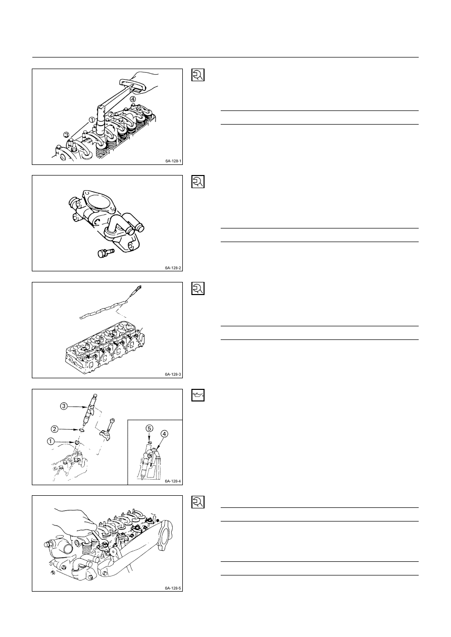
35. Rocker Arm Shaft and Rocker Arm
Tighten the rocker arm shaft bracket bolts in the numerical
order shown in the illustration.
Rocker Arm Shaft Bracket Bolt Torque
kg·m (lb.ft/N·m)
5.5
±
0.5 (39.8
±
3.6/53.9
±
4.9)
36. Thermostat Housing
1) Install the thermostat housing.
2) Tighten the thermostat housing bolts to the specified
torque.
Thermostat Housing Bolt Torque
kg·m (lb.ft/N·m)
1.9
±
0.5 (13.7
±
3.6/18.6
±
4.9)
38. Glow Plug and Glow Plug Connector
1) Install the glow plugs to the cylinder head.
2) Tighten the glow plugs to the specified torque.
Glow Plug Torque
kg·m (lb.ft/N·m)
2.25
±
0.25 (16.3
±
1.8/22.1
±
2.5)
3) Install the glow plug connector.
39. Injection Nozzle Holder
1) Install the injection nozzle gasket
c
and the O-ring
d
to the injection nozzle holder
e
.
Be sure that the O-ring fits snugly in the injection
nozzle groove.
2) Install the nozzle holder toghther with the nozzle holder
bracket
f
to the cylinder head.
Nozzle Holder Bracket Bolt Torque
kg·m (lb.ft/N·m)
3.8
±
0.6 (27.5
±
4.3/37.2
±
5.9)
3) Tighten the holder nut with washer
g
to the specified
torque.
Injection Nozzle Holder Nut Torque
kg·m (lb.ft/N·m)
3.8
±
0.6 (26.0
±
4.3/37.2
±
5.9)
Нет комментариевНе стесняйтесь поделиться с нами вашим ценным мнением.
Текст