Isuzu D-Max / Isuzu Rodeo (TFR/TFS). Manual — part 1317
8–188 ELECTRICAL-BODY AND CHASSIS
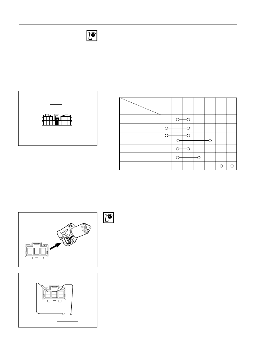
Control Switch Connections
1 2 3
7 8 9 10
11
4
12
5
13
6
14
Terminal
No.
6
3
5
4
2
1
7
SW position
Mist
Off
INT
Lo
Hi
Wash
Wiper Motor Inspection
Connector
INSPECTION AND REPAIR
3
6
2
5
1
4
825RV084
Low Speed Inspection
1. Clamp the wiper motor in a vise.
The moving parts must be clear of the vise.
2. Connect the connector terminals to the battery.
Refer to the illustration.
3. Check the wiper motor low speed operation.
+
−
3
6
2
5
1
4
825RV081
Switch side
C-43

ELECTRICAL-BODY AND CHASSIS 8–189
High Speed Inspection
1. Clamp the wiper motor in a vise.
The moving parts must be clear of the vise.
2. Connect the connector terminals to the battery.
Refer to the illustration.
3. Check the wiper motor high speed operation.
3
6
2
5
1
4
+
−
825RV082
Auto-Stop Inspection
1. Clamp the wiper motor in a vise.
The moving parts must be clear of the vise.
2. Connect the connector terminals to the battery.
Refer to the illustration.
3. Check the wiper motor low speed operation.
4. Disconnect the positive battery terminal.
This will stop the motor.
+
−
3
6
2
5
1
4
825RV081
5. Connect the connector terminals No. 2 and No. 5
with a lead wire.
Refer to the illustration.
6. Reconnect the positive battery terminal to connector
terminal No. 6.
This will restart the motor.
Refer to the illustration.
7. Check the auto-stop operation.
+
−
3
6
2
5
1
4
825RV080
Washer Motor Inspection
1. Fill the washer tank with washing solution.
2. Disconnect the motor connector.
3. Apply battery voltage to the washer motor
connector.
4. Check the washer motor operation.
825RV079
8–190 ELECTRICAL-BODY AND CHASSIS
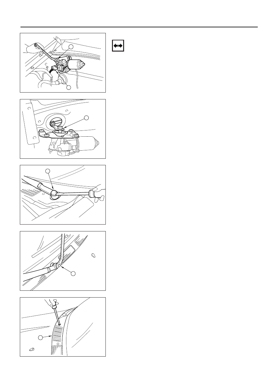
WIPER MOTOR AND LINKAGE
Removal
1. Disconnect the wiper motor connector
1.
2. Remove the wiper motor bracket screws 2.
1
2
825RV069
3. Disconnect the wiper motor from the wiper linkage at
the crank arm 3.
3
825RV070
4. Disconnect the wiper arm nut cap 4.
4
825RV071
5. Remove the wiper arm nut 5.
6. Remove the wiper arm with blade.
5
825RV072
7. Remove the vent cowl cover 6.
6
825RV073
ELECTRICAL-BODY AND CHASSIS 8–191
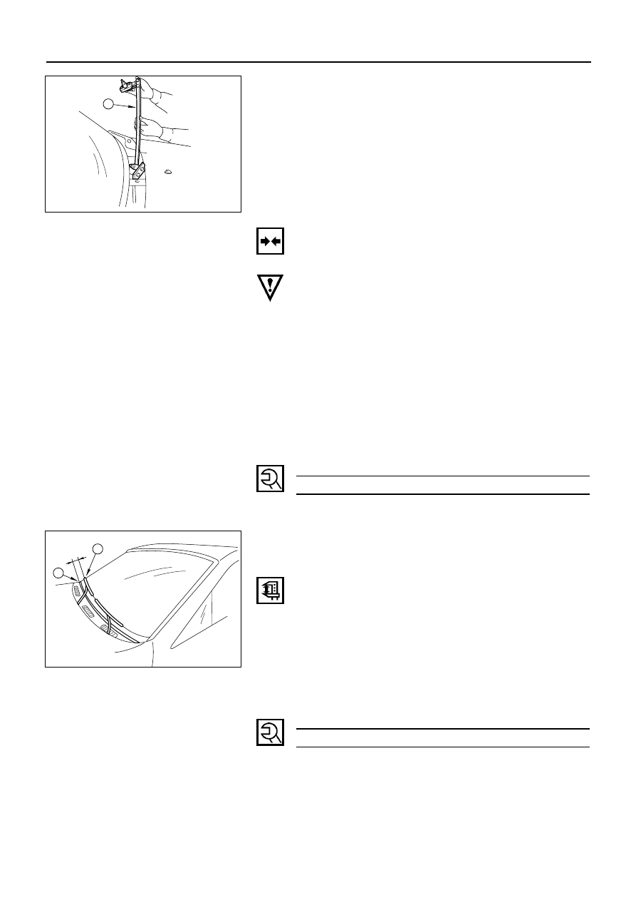
8. Remove the wiper linkage 7 from the access hole.
7
825RV074
Installation
Follow the removal procedure in the reverse order to
install the wiper motor and linkage.
Pay close attention to the important points mentioned in
the following paragraphs.
Wiper Linkage
Take care not to scratch the painted surfaces of the body
when installing the wiper linkage to the body.
In case crank arm of wiper motor is removed, confirm the
position of auto stop prior to reinstall the crank arm to the
wiper motor.
Crank Arm Nut Torque
kg·m (lb·ft/N·m)
1.4 ±0.2 (10 ± 1.4/13.7 ± 2.0)
Wiper Blade Position
Confirm the auto stop position of wiper motor prior to the
installation of the wiper blade and arm.
The distance between the vent cowl cover rubber seal 1
and the wiper blade edge 2 is about 45 mm (1.8 in).
1
2
825RV075
Wiper Arm Nut
Tighten the wiper arm nut to the specified torque.
Wiper Arm Nut Torque
kg·m (lb·ft/N·m)
1.4 ± 0.2 (10 ± 1.4/13.7 ± 2.0)
Нет комментариевНе стесняйтесь поделиться с нами вашим ценным мнением.
Текст