Isuzu D-Max / Isuzu Rodeo (TFR/TFS). Manual — part 12
4JA1-TC/4JH1-TC ENGINE DRIVEABILITY AND EMISSIONS
6E–43
45
45
Data Link Connector
(No. 6)
BLU
Less than 1V
Battery voltage
Connect
DC V
45
GND
46
46
No Connection
BRN/RED
-
-
-
-
-
-
-
-
47
47
No Connection
-
-
-
-
-
-
-
-
-
48
48
No Connection
-
-
-
-
-
-
-
-
-
49
49
Throttle Position
Sensor (TPS) Ground
RED/GRN
Idle: Approx.
0.4k
Ω/
WOT: Approx.
3.8k
Ω
-
-
-
Disconnect
Ω
38
49
50
50
No Connection
-
-
-
-
-
-
-
-
-
51
51
No Connection
-
-
-
-
-
-
-
-
-
52
52
No Connection
-
-
-
-
-
-
-
-
-
53
53
No Connection
-
-
-
-
-
-
-
-
-
54
54
No Connection
-
-
-
-
-
-
-
-
-
55
55
No Connection
-
-
-
-
-
-
-
-
-
56
56
No Connection
-
-
-
-
-
-
-
-
-
57
57
Throttle Position
Sensor (TPS) Power
Supply
BLK/GRN
Less than 1V
Approx. 5V
Connect
DC V
57
49
58
58
ECM Main Relay
BLU/BLK
Battery
voltage
Less than 1V
Connect
DC V
58
GND
59
59
No Connection
-
-
-
-
-
-
-
-
-
60
60
No Connection
-
-
-
-
-
-
-
-
-
61
61
No Connection
-
-
-
-
-
-
-
-
-
62
62
No Connection
-
-
-
-
-
-
-
-
-
63
63
ECM Power Supply
BLU/RED
Less than 1V
Battery voltage
Connect
DC V
63
GND
64
64
No Connection
-
-
-
-
-
-
-
-
-
65
65
Brake Switch 2 Signal
WHT/BLK
Less than 1V
Battery voltage when pedal is not
stepped on
Connect
DC V
65
GND
66
66
No Connection
-
-
-
-
-
-
-
-
-
67
67
No Connection
-
-
-
-
-
-
-
-
-
68
68
Vehicle Speed Sensor
(VSS) Via Speed Meter
BLU/WHT
-
Approx. 15Hz by wave form or
approx. 6.4V at vehicle speed 20km/
h
Connect
AC V
68
GND
69
69
Idle Switch
GRN/BLK
Less than 1V
Approx. 5V when pedal is stepped on
Connect
DC V
69
GND
70
70
No Connection
-
-
-
-
-
-
-
-
-
71
71
No Connection
-
-
-
-
-
-
-
-
-
72
72
No Connection
-
-
-
-
-
-
-
-
-
73
73
No Connection
-
-
-
-
-
-
-
-
-
74
74
No Connection
-
-
-
-
-
-
-
-
-
75
75
No Connection
-
-
-
-
-
-
-
-
-
76
76
No Connection
-
-
-
-
-
-
-
-
-
77
77
No Connection
-
-
-
-
-
-
-
-
-
78
78
No Connection
-
-
-
-
-
-
-
-
-
79
79
No Connection
-
-
-
-
-
-
-
-
-
80
80
No Connection
-
-
-
-
-
-
-
-
-
81
81
No Connection
-
-
-
-
-
-
-
-
-
82
82
No Connection
-
-
-
-
-
-
-
-
-
83
83
Mass Air Flow (MAF)
Sensor Power Supply
WHT/RED
Less than 1V
Approx. 5V
Connect
DC V
83
92
84
84
Intake Air Temperature
(IAT) Sensor Signal
BLK/BLU
Less than 1V
Approx. 2.5V at IAT 25°C
Connect
DC V
84
92
Pin
No.
B/Box
No.
Pin Function
Wire
Color
Signal or Continuity
ECM
Connection
Tester Position
Key SW Off
Key SW
On
Engine
Idle
Engine
2000rpm
Range
(+)
(-)

6E–44
4JA1-TC/4JH1-TC ENGINE DRIVEABILITY AND EMISSIONS
85
85
No Connection
-
-
-
-
-
-
-
-
-
86
86
No Connection
-
-
-
-
-
-
-
-
-
87
87
Neutral Switch
BLK/WHT
Less than 1V
Battery voltage at other than neutral
(MT) / Battery voltage in P or N (AT)
Connect
DC V
87
GND
88
88
Mass Air Flow (MAF)
Sensor Signal
GRN/RED
Less than 1V
Approx. 1V Approx. 2V Approx. 3V
Connect
DC V
88
92
89
89
Engine Coolant
Temperature (ECT)
Sensor Signal
GRY
Less than 1V
Approx. 1.3V at ECT 80°C
Connect
DC V
89
93
90
90
TDC Sensor Signal
RED
-
-
Approx.
47Hz by
wave form
or approx.
0.7V at
700rpm
Approx.
133Hz by
wave form
or approx.
1.0V
Connect
AC V
90
98
91
91
TDC Sensor Output To
Pump Control Unit
(PSG) No.8
PNK
-
-
Approx.
47Hz by
wave form
Approx.
133Hz by
wave form
-
-
-
-
92
92
Mass Air Flow (MAF)
Sensor Ground
BLK/RED
Continuity
with ground
-
-
-
Connect
Ω
92
GND
93
93
Engine Coolant
Temperature (ECT)
Sensor Ground
BLK/PNK
Continuity
with ground
-
-
-
Connect
Ω
93
GND
94
94
Glow Relay
BLK/BLU
Less than 1V
Battery voltage when glow system is
not activated
Connect
DC V
94
GND
95
95
No Connection
-
-
-
-
-
-
-
-
-
96
96
No Connection
-
-
-
-
-
-
-
-
-
97
97
EGR EVRV
BLK/ORG
-
Approx. 140Hz by wave
form when EVRV is
activated
-
-
-
-
98
98
TDC Sensor Ground
WHT
Continuity
with ground
-
-
-
Connect
Ω
98
GND
99
99
CAN (Controller Area
Network) to PSG No.1
RED
-
-
-
-
-
-
-
-
100
100
CAN (Controller Area
Network) to PSG No.2
WHT
-
-
-
-
-
-
-
-
101
101
TDC Sensor Shield
Line
-
Continuity
with ground
-
-
-
Connect
Ω
101
GND
102
102
No Connection
-
-
-
-
-
-
-
-
-
103
103
No Connection
-
-
-
-
-
-
-
-
-
104
104
No Connection
-
-
-
-
-
-
-
-
-
105
105
Solenoid Valve Shut
Off (MAB) Output
Signal to PSG No.5
ORG
-
Wave form
-
-
-
-
Pin
No.
B/Box
No.
Pin Function
Wire
Color
Signal or Continuity
ECM
Connection
Tester Position
Key SW Off
Key SW
On
Engine
Idle
Engine
2000rpm
Range
(+)
(-)
4JA1-TC/4JH1-TC ENGINE DRIVEABILITY AND EMISSIONS
6E–45
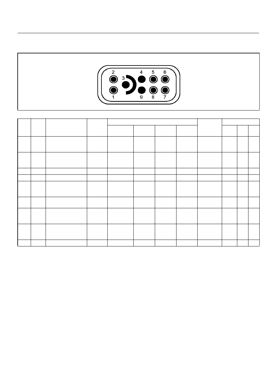
PSG CONNECTOR PIN ASSIGNMENT & OUTPUT SIGNAL (4JH1-TC)
View Looking Into PSG Case
Pin
No.
B/Box
No.
Pin Function
Wire
Color
Signal or Continuity
PSG
Connection
Tester Position
Key SW Off
Key SW
On
Engine
Idle
Engine
2000rpm
Range
(+)
(-)
1
99
CAN (Controller Area
Network) to ECM
No.99
RED
Continuity
between
ECM & PSG
-
-
-
Disconnect
Ω
1
99
2
100
CAN (Controller Area
Network) to ECM
No.100
WHT
Continuity
between
ECM & PSG
-
-
-
Disconnect
Ω
2
100
3
-
No Connection
-
-
-
-
-
-
-
-
-
4
-
No Connection
-
-
-
-
-
-
-
-
-
5
105
Solenoid Valve Shut
Off (MAB) Output
Signal to ECM No.105
ORG Continuity
between
ECM & PSG
-
-
-
Disconnect
Ω
5
105
6
-
Ground
BLK
Continuity
with ground
-
-
-
Disconnect
Ω
6
GN
D
7
3
Battery Power Supply
BLU/RED
Continuity
between
ECM & PSG
-
-
-
Disconnect
Ω
7
3
8
91
TDC Sensor Output
ECM No.91 To Pump
Control Unit (PSG)
PNK
Continuity
between
ECM & PSG
-
-
-
Disconnect
Ω
8
91
9
-
No Connection
-
-
-
-
-
-
-
-
-

6E–46
4JA1-TC/4JH1-TC ENGINE DRIVEABILITY AND EMISSIONS
GENERAL DESCRIPTION FOR ECM AND
SENSORS
Engine Control Module (ECM)
The engine control module (ECM) is located on the
transmission tunnel.
The fuel quantity and injection timing related functions
are controlled by the pump control unit (PSG).
The engine control module (ECM) performs the
following functions.
• Control of the exhaust gas re-circulation (EGR)
• Control of the quick on start (QOS) glow control
system
• Control of the A/C compressor
• Execution of the immobiliser function
Pump Control Unit (PSG) & Data Exchange
Between Control Module
The radial plunger distributor type injection pump uses
two control modules to execute full control of the engine
management system.
• Engine Control Module (ECM)
• Pump Control Unit (PSG) = Pumpen Steuer Great
(German)
The pump control unit (PSG) receives signals from the
sensors inside the pump to determine the cam ring
rotation angle, the pump speed and the fuel
temperature .
These values are then compared to the desired values
sent by the engine control module (ECM) such as the
desired injection timing and the desired fuel injection
quantity.
The engine control module (ECM) processes all engine
data and data regarding the surrounding environment
received from external sensors to perform any engine
side adjustments.
Maps for both are encoded in both control units. The
control units input circuit process sensor data.
A Microprocessor then determines the operating
conditions and calculates set values for optimum
running.
The interchange of data between the engine control
module (ECM) and the pump control unit (PSG) is
perfumed via a CAN-bus system. The abbreviation CAN
stands for Controller Area Network. By having two
separate control modules, the high pressure solenoid
valve. This prevents the discharge of any disturbing
signals.
The following signals are exchanged via the CAN-bus:
From ECM to PSG
• Desired injection quantity
• Desired injection timing
• Engine speed
From PSG to ECM
• Fuel temperature
• Pump speed
• Cylinder identifier
• Control pulse (actual injection quantity + actual
injection timing)
• PSG status
Self Diagnosis / Interface / Signal
To High Pressure Solenoid
Engine Speed
Injection Timing
Accelerator Pedal
Injection Quantity
Intake Air Temperature
Response Signal
Mass Air Flow
Additional Signal
Others
Additional Operations To Timing Control Valve (TCV)
Engine
Control
Module
(ECM
Cam Ring Rotational Angle
Fuel Temperature
High Pressure
Solenoid Valve
Pump
Control Fuel Injection
Unit (Mechanical)
(PSG
Timing Device
Нет комментариевНе стесняйтесь поделиться с нами вашим ценным мнением.
Текст