Isuzu D-Max / Isuzu Rodeo (TFR/TFS). Manual — part 17
4JA1-TC/4JH1-TC ENGINE DRIVEABILITY AND EMISSIONS
6E–63
DIAGNOSIS WITH Tech 2
If no codes are set:
• Refer to F1: Data Display and identify the electrical
faults that are not indicated by trouble code.
• Refer to “SYMPTOM DIAGNOSIS”.
If codes are set:
1. Record all trouble codes displayed by Tech 2 and
check id the codes are intermittent.
2. Clear the codes.
3. Drive the vehicle for a test to reproduce the faulty
status.
4. Check trouble codes again using the Tech 2.
5. If no codes is displayed by test driving, the fault is
intermittent. In this case, refer to “DIAGNOSIS
AIDS”.
6. If a code is present, refer to DTC Chart for
diagnosis.
7. Check trouble codes again using the Tech 2.
Tech 2 CONNECTION
Tech 2 scan tool is used to electrically diagnose the
automatic transmission system and to check the
system. The Tech 2 enhances the diagnosis efficiency
though all the troubleshooting can be done without the
Tech 2.
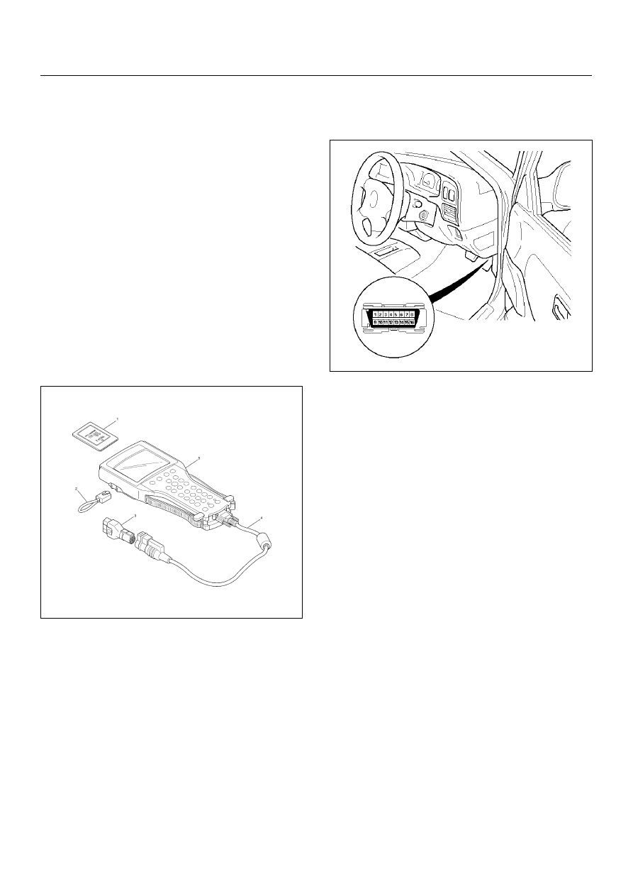
1. Configuration of Tech 2
• Tech 2 scan tool kit (No. 7000086), Tech 2 scan
tool (No. 7000057) and DLC cable (No. 3000095).
• SAE 16/19 adapter (No. 3000098) (3), RS232
loop back connector (No. 3000112) (2) and
PCMCIA card (No. 3000117) (1).
2. Tech 2 Connection
• Check the key switch is turn OFF.
• Insert the PCMCIA card (1) into the Tech 2 (5).
• Connect the SAE 16/19 adapter (3) to the DLC
cable (4).
• Connect the DLC cable (4) to the Tech 2 (5).
• Connect the SAE 16/19 adapter (3) to the data
link connector of the vehicle.
• Turn the key switch of the vehicle ON and press
the “PWR” key of the Tech 2.
• Check the display of the Tech 2.
NOTE: Be sure to check that the power is not supplied
to the Tech 2 when attaching or removing the PCMCIA
card.
6E–64
4JA1-TC/4JH1-TC ENGINE DRIVEABILITY AND EMISSIONS
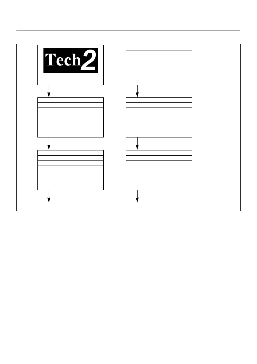
TECH 2 OPERATING FLOW CART (START UP)
Select “4JA1-TC Bosch” or “4JH1-TC Bosch” in Vehicle Identification menu and the following table is shown in the
Tech 2 screen.
Main Menu
F0: Diagnostic
F1: Service Programming System (SPS)
F2: View Capture Data
F3: Tool Option
F4: Download/ Upload Help
Press “ENTER” key.
Vehicle Identification
(3) 2003
(2) 2002
(1) 2001
(Y) 2000
(X) 1999
(W) 1998
Select “F0: Diagnostic”.
Select “(2) 2002”or later.
Press (ENTER) to Continue
System Selection Menu
F0: Powertrain
F1: Chassis
F3: Body
Select “(TF/UC)”.
Vehicle Identification
4JH1-TC Bosch
4JA1-TC Bosch
4JH1-T Denso
3.5L V6 6VE1 Hitachi
AW30-40LE
AT JR405E
Select “F0: Powertrain”.
Select “4JH1-TC Bosch”.
Vehicle Identification
(UB) Trooper, Bighorn
(UE) Rodeo,/Amigo, Wizard/Mu
(TF/UC) LUV, Frontier, LAO-Rodeo
(TBR)
(N*) ELF, NPR, NQR
or “4JH1-TC Bosch”.

4JA1-TC/4JH1-TC ENGINE DRIVEABILITY AND EMISSIONS
6E–65
F0: Diagnostic Trouble Code
The purpose of the “Diagnostic Trouble Codes” mode is
to display stored trouble code in the ECM.
When “Clear DTC Information” is selected, a “Clear
DTC Information”, warning screen appears.
This screen informs you that by cleaning DTC's “all
stored DTC information in the ECM will be erased”.
After clearing codes, confirm system operation by test
driving the vehicle.
Symptom Code:
This number or alphabet means identification of the
malfunction. Each DTC includes plural symptoms, such
as DTC P0100 has four kinds of symptom code (7), (9),
(B) and (C). DTC chart (check procedure) is separated
depending on the symptom code.
F1: Data Display
The purpose of the “Data Display” mode is to
continuously monitor data parameters.
The current actual values of all important sensors and
signals in the system are display through F1 mode.
See the “Typical Scan Data” section.
F2: Snapshot
“Snapshot” allows you to focus on making the condition
occur, rather than trying to view all of the data in
anticipation of the fault.
The snapshot will collect parameter information around
a trigger point that you select.
F3: Miscellaneous Test:
The purpose of “Miscellaneous Test” mode is to check
for correct operation of electronic system actuators.
F4: Programming (Factory Use Only)
The purpose of “Programming” is to program VIN in the
ECM and lock the programmed data.
F0: Diagnostic Trouble Codes
F0: Read DTC Infor As Stored By ECU
F1: Clear DTC Information
F1: Data Display
F2: Snapshot
F3: Miscellaneous Test
F0: Lamps
F0: Check Light
F1: Glow Time Telltale Test
F1: Relays
F0: Glow Time Relay Test
F2: Engine Speed (RPM) Control
F4: Programming
F0: Program VIN
F1: Lock ECU
Read DTC Infor As Stored By ECU
P0100 Present
(7) Mass Air Flow (MAF) Sensor
Voltage Supply Circuit High Input
DTC No.
Symptom Code

6E–66
4JA1-TC/4JH1-TC ENGINE DRIVEABILITY AND EMISSIONS
TYPICAL SCAN DATA & DEFINITIONS 4JA1-TC (ENGINE DATA)
Use the Typical Values Table only after the On-Board Diagnostic System Check has been completed, no DTC(s) were
noted, and you have determined that the on-board diagnostics are functioning properly. Tech 2 values from a
properly-running engine may be used for comparison with the engine you are diagnosing.
Condition : Vehicle stopping, engine running, air conditioning off & after warm-up (Coolant temperature approximately
80 deg.)
Tech 2/TIS 2000
Parameter
Units
Idle
1500rpm
2000rpm
Description
1
Engine Speed
rpm
705 - 755
1475 - 1525
1975 - 2025
The engine speed is measured by ECM from the CKP
sensor.
2
Vehicle
Speed
km/h
0
0
0
This displays vehicle speed. The vehicle speed is
measured by ECM from the vehicle speed sensor.
3
Pump Speed
rpm
353 - 375
725 - 775
975 - 1025
This displays injection pump speed. The injection speed
is measured by ECM from the pump cam sensor.
4
Accelerator
Position Signal
%
0
5 - 7
7 - 9
Throttle position operating angle is measured by the
ECM from throttle position output voltage. This should
display 0% at idle and 99 - 100% at full throttle.
5
Idle Switch
Active/ Inactive
Active
Active
Inactive
This displays operating status of the idle switch. This
should display “Active” when the idle condition.
6
Mass Air Flow
Sensor
mg/strk
380 - 430
360 - 390
360 - 390
This displays intake air amount. The mass air flow is
measured by ECM from the MAF sensor output voltage.
7
Barometric
Pressure
hpa
990 - 1015
990 - 1015
990 - 1015
The barometric pressure is measured by ECM from the
sensor in the ECM. This data is changing by altitude.
8
Desired Injection
Quantity
mg/stk
8 - 10
8 - 11
8 - 11
This displays commanded value from the ECM. The ECM
compensates for fuel rate to basic rate.
9
Injection Quantity
mg/stk
8 - 10
8 - 11
8 - 11
This displays actual fuel quantity. The PSG controls high
pressure solenoid valve to meet commanded value from
the ECM.
10
Desired Fuel
Injection Start
°CA
2 - 3
3 - 4
3 - 4
This displays commanded value from the ECM. The ECM
compensates for fuel injection timing by throttle position
and various sensor signal.
11
Actual Injection
Start
°CA
2 - 3
3 - 4
3 - 4
This displays actual injection timing value controlled by
the TCV. The TCV controls duty ratio to meet
commanded value from the PSG.
12
Coolant
Temperature
°C
80 - 85
80 - 85
80 - 85
The ECT is measured by ECM from ECT sensor output
voltage. This data is changing by coolant temperature.
When the engine is normally warm upped, this data
displays approximately 80 deg.
13
Fuel Temperature
°C
25 - 50
25 - 50
25 - 50
The FT is measured by PSG from FT sensor. This data is
changing by fuel temperature.
14
Intake Air
Temperature
°C
25 - 50
25 - 50
25 - 50
The IAT is measured by ECM from IAT sensor output
voltage. This data is changing by intake air temperature.
15
Ignition Status
On12V/ Off0V
On 12V
On 12V
On 12V
This displays the key switch status indicated by the ECM
with key switch signal. This should display “Off 0V” at key
OFF and “On12V” at key ON.
16
Brake Switch 1
Active/ Inactive
Inactive
Inactive
Inactive
This displays operating status of the brake switch. This
should display “Active” when the brake pedal is stepped
on.
17
Brake Switch 2
Active/ Inactive
Inactive
Inactive
Inactive
This displays operating status of the brake switch. This
should display “Active” when the brake pedal is stepped
on.
18
Clutch Switch
Active/ Inactive
Inactive
Inactive
Inactive
This displays operating status of the clutch switch. This
should display “Active” when the clutch pedal is stepped
on.
19
Neutral Switch
On/Off
On
On
On
This displays operating status of the neutral switch. This
should display “On” when the gear position is neutral.
20
A/C Information
Switch
Active 12V/
Inactive 0V
Inactive 0V
Inactive 0V
Inactive 0V
This displays the air conditioner request signal. This
should display “Active 12V” when the air conditioner
switch is switched on.
Нет комментариевНе стесняйтесь поделиться с нами вашим ценным мнением.
Текст