Isuzu D-Max / Isuzu Rodeo (TFR/TFS). Manual — part 1724

6H-2 ENGINE SPEED CONTROL SYSTEM
Service Precaution
CAUTION:
Always use the correct fastener in the proper location.
When you replace a fastener, use ONLY the exact part
number for that application. ISUZU will call out those
fasteners that require a replacement after removal. ISUZU
will also call out the fasteners that require thread lockers
or thread sealant. UNLESS OTHERWISE SPECIFIED, do
not use supplemental coatings (Paints, greases, or other
corrosion inhibitors) on threaded fasteners or fastener
joint interfaces. Generally, such coatings adversely affect
the fastener torque and the joint clamping force, and may
damage the fastener. When you install fasteners, use the
correct tightening sequence and specifications. Following
these instructions can help you avoid damage to parts and
systems.
Accelerator Pedal Control Cable
Removal
1. Loosen the adjust nut on the cable bracket mounted.
2. Remove cable clip (3).
3. Disconnect accelerator pedal (AP) control cable (5). (on
throttle valve side)
4. Disconnect AP control cable (1). (on AP pedal (7) side)
5. Remove grommet (2).
6. Remove AP control cable (4).
Inspection
Check the following items, and replace the control cable if any
abnormality is found:
• The control cable should move smoothly.
• The control cable should not be bent or kinked.
• The control cable should be free of damage and corrosion.
Installation
1. Install AP control cable (4).
2. Install grommet (2).
3. Connect AP control cable (1). (on AP (7) side)
4. Connect AP control cable (5). (on throttle valve side)
5. Install cable clip (3).
6. Install adjusting nut.
7. Confirm the free play of throttle valve and control valve.
Free Play: 3 to 8 mm (0.117 to 0.312 in)
ENGINE SPEED CONTROL SYSTEM 6H-3
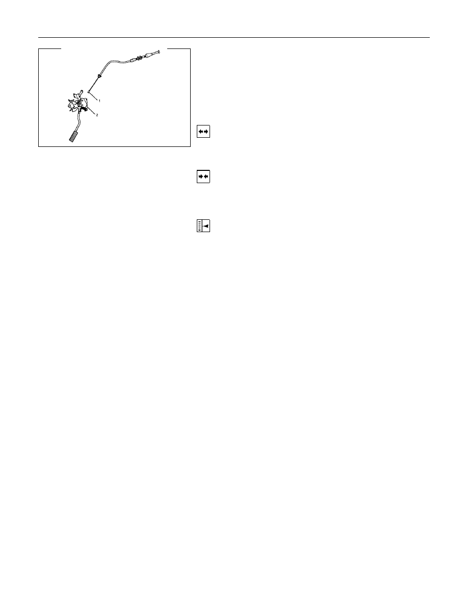
Accelerator Pedal
Accelerator Pedal and Associated Parts
Legend
1 Accelerator Pedal Control Cable
2 Accelerator Pedal Assembly
Removal
1. Accelerator pedal control cable (1).
2. Accelerator pedal assembly (2).
Installation
1. Accelerator pedal assembly (2).
2. Accelerator pedal control cable (1).
Adjustment
Manual Transmission:
• Rotate counterclockwise to loosen the locked nut and screw
the stopper bolt in sufficiently.
• Fully depress the pedal and hold it there by hand. Next,
rotate the stopper bolt until it hits the stopper of pedal
bracket. Then, lock the stopper bolt there.
INDUCTION 6J-1
SECTION 6J
INDUCTION
CONTENTS
PAGE
Service Precaution . . . . . . . . . . . . . . . . . . . . . . . . . . . 6J- 2
Air Cleaner Filter. . . . . . . . . . . . . . . . . . . . . . . . . . . . 6J- 2
Removal. . . . . . . . . . . . . . . . . . . . . . . . . . . . . .. 6J- 2
Inspection. . . . . . . . . . . . . . . . . . . . . . . . . . . . ... 6J- 2
Installation. . . . . . . . . . . . . . . . . . . . . . . . . . . . .. 6J- 2

6J-2 INDUCTION
Service Precaution
CAUTION:
Always use the correct fastener in the proper location.
When you replace a fastener, use ONLY the exact part
number for that application. ISUZU will call out those
fasteners that require a replacement after removal. ISUZU
will also call out the fasteners that require thread lockers
or thread sealant. UNLESS OTHERWISE SPECIFIED, do
not use supplemental coatings (Paints, greases, or other
corrosion inhibitors) on threaded fasteners or fastener
joint interfaces. Generally, such coatings adversely affect
the fastener torque and the joint clamping force, and may
damage the fastener. When you install fasteners, use the
correct tightening sequence and specifications. Following
these instructions can help you avoid damage to parts and
systems.
Air Cleaner Filter
Removal
1. Remove positive ventilation hose connector.
2. Remove intake air temperature sensor.
3. Remove mass air flow sensor.
4. Remove air cleaner duct assembly.
5. Remove air cleaner element.
Inspection
Check the air cleaner filter for damage or dust clogging.
Replace if it is damaged, or clean if it is clogged.
Cleaning Method
Tap the air cleaner filter gently so as not to damage the paper
filter, or clean the element by blowing with compressed air of
about 490 kPa (71 psi) from the clean side if it is extremely
dirty.
Installation
1. Install air cleaner element.
2. Attach the air cleaner duct cover to the body completely,
then clamp it with the clip.
3. Install mass air flow sensor.
4. Install mass air temperature sensor.
5. Install positive crankcase ventilation hose connector.
Нет комментариевНе стесняйтесь поделиться с нами вашим ценным мнением.
Текст