Isuzu D-Max / Isuzu Rodeo (TFR/TFS). Manual — part 1142
ELECTRICAL-BODY AND CHASSIS 8-325
REMOVAL AND INSTALLATION
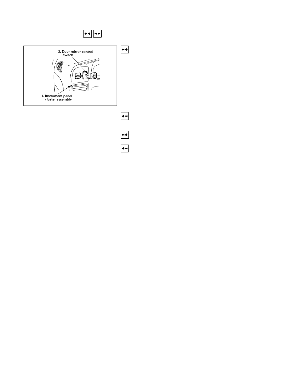
DOOR MIRROR CONTROL SWITCH
Removal
1.Instrument Panel Cluster Assembly
• Refer to section 10 “BODY” for instrument panel cluster
assembly removal steps.
2.Door Mirror Control Switch
• Disconnect the switch connector.
• To remove the switch, push the lock from the back side
of the cluster assembly.
Installation
To install, follow the removal steps in the reverse order.
DOOR MIRROR
Removal and Installation
Refer to the DOOR MIRROR in section 10 “BODY”.
8-326 ELECTRICAL-BODY AND CHASSIS
INSPECTION AND REPAIR
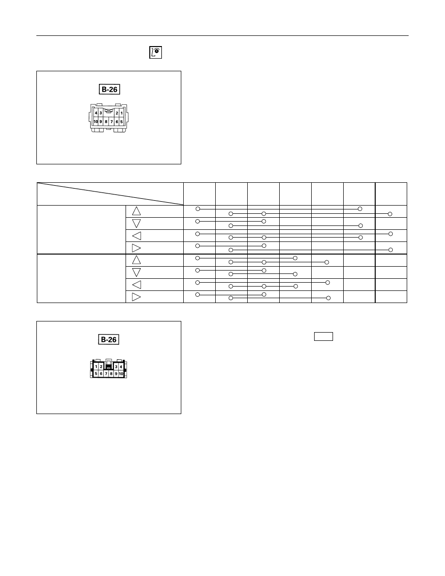
Switch side
Door Mirror Control Switch
1.Switch side Connector Circuit
Check continuity between the switch connector terminals
while operating the door mirror control switch as shown in
the following table.
Connector No.
Switch position
4
9
1
8
10
7
5
(Up)
(Down)
(Left)
(Right)
(Up)
(Down)
(Left)
(Right)
Harness side
2.Harness Side Connector Circuit
Remove the connector No.
B-26
of the mirror control
switch and check voltage and continuity of the harness side
connector.
• When there is no continuity at the terminal No. 5, 7, 8
and 10, it is considered that the circuit with terminal No.
1 (B/W) is defective.
Door mirror (RH)
Door mirror (LH)
ELECTRICAL-BODY AND CHASSIS 8-327
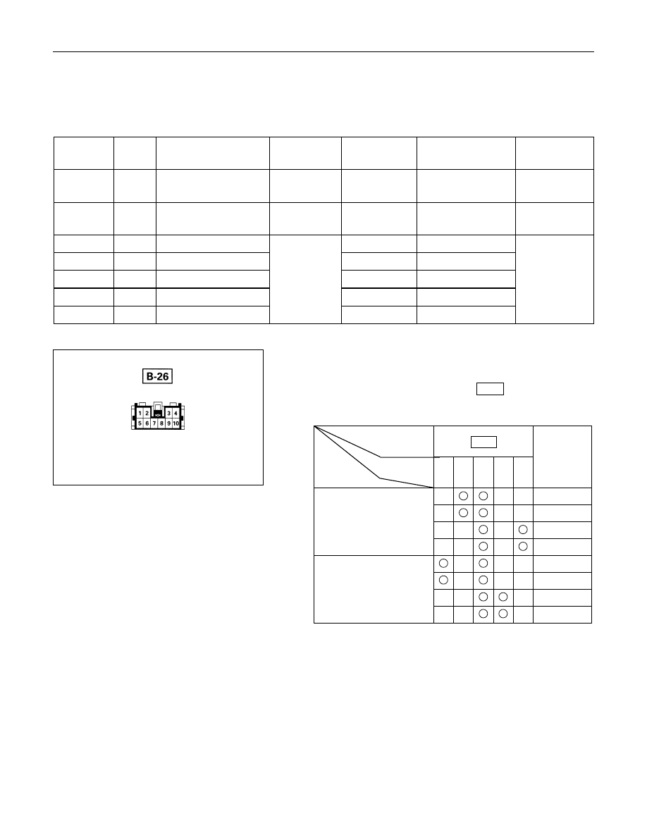
• When there is no continuity at either one of the circuit
No, 5, 7, 8, or 10, the motor in the mirror of the circuit or
the circuit itself is defective.
Terminal
No.
Wire
color
Connection to
Check item
Connecting
terminal
Check condition
Standard
1
B/W
LH mirror & RH
mirror
Continuity
1-Ground
-
No continuity
4
R/L
Fuse CB-19 (15A)
Voltage
4-Ground
Starter SW “ACC”
position
Approx.
12V
5
V
RH mirror-LH/RH
5-1
-
7
W/B
RH mirror-Up/Down
7-1
-
8
W/G
LH mirror-Up/Down
Continuity
8-1
-
Continuity
9
B
Ground
9-Ground
-
10
B/R
LH mirror-LH/RH
10-1
-
Harness side
Door Mirror
1.Door Mirror Control Switch Connector Circuit
Disconnect the switch connector (
B-26
), apply the battery
voltage to the harness side connector terminals and check
its function.
Connector
No.
B-26
Operating
Terminal
Mirror
No.
10
5
1
8
7
direction
+
-
Left
-
+
Right
-
+
Up
+
-
Down
+
-
Left
-
+
Right
-
+
Up
+
-
Down
Left
Right
8-328 ELECTRICAL-BODY AND CHASSIS
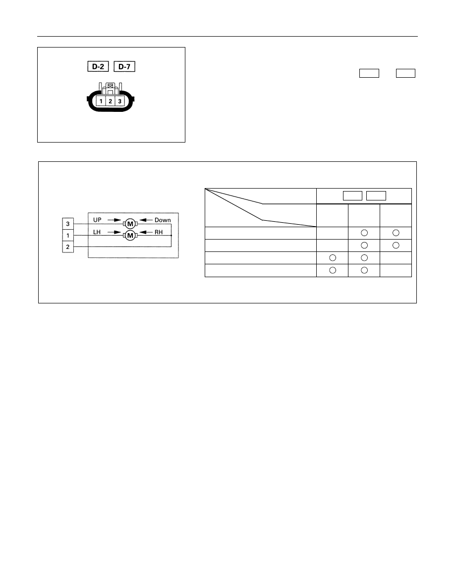
Door mirror side
2.Door Mirror Connector Circuit
Disconnect the door mirror connector, apply the battery
voltage to the door mirror side connector (
D-2
and
D-7
)
terminals and check its function.
Connector No.
D-2
D-7
Terminal No.
Operation
1
2
3
Up
-
+
Down
+
-
Left
+
-
Right
-
+
Нет комментариевНе стесняйтесь поделиться с нами вашим ценным мнением.
Текст