Isuzu D-Max / Isuzu Rodeo (TFR/TFS). Manual — part 1326

8–224 ELECTRICAL-BODY AND CHASSIS
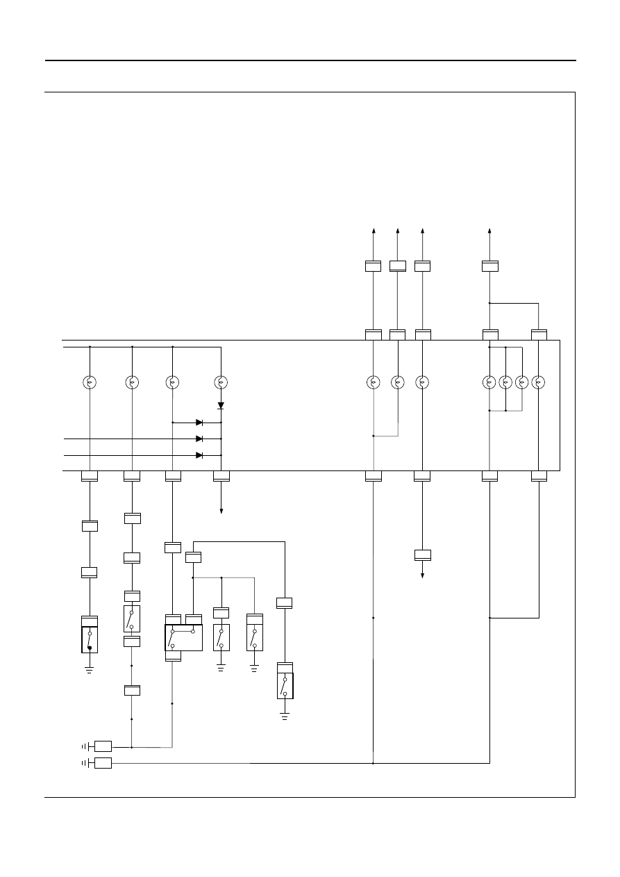
CIRCUIT DIAGRAM (W/ TACHOMETER – DIESEL ENGINE (RHD))
D08RVA02
TIMING BELT
3
F-1
P-1
P-5
30B/Y
+
_
B2
OFF
IG2
ACC
STARTER SW
B1
ST
IG1
6
3 B/R
3 B/R
CB-5
15A METER
IGN B1
40A
P-2
P-10
P-7
5B/Y
ENG.
FRAME
1
0.5 B
0.85 B
0.85 B
0.5 B
F-1
1
0.3 P
0.5 Y/R
11
THERMO UNIT
0.5 Y/B
0.5 Y/B
4
1
3
0.5 B/R
0.5 Y/B
9
12
2
3
H-4
11
H-9
5
H-8
0.85 B
1
5
11
TACHOMETER
FUEL
B-23
B-24
B-23
E-19
E-44
H-4
17
H-9
E-44
E-44
F-1
H-4
H-4
1
0.5 B/R
0.5P
H-15
VEHICLE SPEED
SENSOR
H-6
14
QOS-II
CONTROL UNIT(7)
0.3 O/L
C-41
4
H-7
0.85Y
0.85Y
SPEEDOMETER
FUEL GAUGE
ENGINE COOLANT
TEMPERATURE GAUGE
GLOW
SEDIMENTER
0.85 Y
0.85 B
0.85 B
1.25
FENDER-LH
C-36
FENDER-RH
C-2
6
B-24
5
B-23
B-23
16
B-24
8
FUEL TANK UNIT
0.5 BR/Y
0.5 BR/Y
0.5 L/B
0.5 L/B
0.5 L/B
H-15
8
10
H-9
H-15
7
0.5 Y/R
2
3 W/B
15B/R
0.85Y
0.85Y
10
H-6
22
H-6
16
H-6
17
H-6
METER
0.3 P
0.5 Y/R
7
H-4
0.5 B/R
2
E-36
0.5 B
TACHO SENSOR
1
FUEL FILTER SW
C - 51
C - 52
0.5 B
1.25 B
E-36
B-24
9
H-8
8
1
3
C-41
2
B-24
矢崎
E-3110-8
'96/ 10/ 2
'96/ 10/ 2
D 0 8 R V A 0 2
T F A
'97 TFR/S EXP.-RHD
METER(DIE.W/ TACHO)-1
大野
資料区分
品名 又は
電装タイトル
ユニットタイプ
対象車型
いすゞ品番
J−No.
イラスト番号・追番
B K T G S
イラスト区分
資料番号(Pub.No.)
L D C
W O Y T S
発注者
受注番号
発注日
希望納期
イラストサイズ
×
パーツイラスト番号
イラスト担当
180
240
4556
作業番号
ELECTRICAL-BODY AND CHASSIS 8–225
D08RVA04
R-4
1
2
C-37
C-37
1
H-9
16
H-8
3
B-23
RELAY;CHARGE(5) OR
AC GENERATOR(L)
B-23
13
CHARGE
0.85 W/L
C-39
BRAKE FLUID LEVEL SW
H-6
H-6
H-6
20
7
2
H-6
5
4WD SW
1.25B
1
1
B-23
12
B-24
15
H-4
H-4
TURN-LH
TURN-RH
4WD
BRAKE
E-45
E-46
12
H-4
DIMMER
・PASSING SW
ILLUMINATION
1
0.3 P/B
0.5 P/B
0.5 P/G
0.5 P/G
0.5 P/G
0.5 P/G
4
HIGH BEAM
B-24
1
C-37
B-23
15
0.5B
0.5B
1.25B
1.25B
0.85B
0. 5R/B
B-24
14
3
COMBINATION SW
HAZARD WARNING SW
1
0.85G/W
FUSE EB-8
3
B-23
B-23
COMBINATION SW
HAZARD WARNING SW
16
0.85G/W
B-24
RELAY;TAIL(1)
13
0.85 G/R
B-24
14
B-23
0.85 G/R
0.85B
0.85B
0.5B
0.5B
0.5P/G
1.25B
15
1
BODY-RH
C-2
B-28
FENDER-RH
VACUUM SW
PARKING BRAKE SW(4
×
2)
PARKING BRAKE SW(4
×
4)
1
C-38
OIL PRESSURE SW
1
E-1
0.5R/W
0.3L/R
B-23
10
OIL PRESSURE
0.3L
0.5L
0.5L
0.5L/R
0.5L/R
矢崎
E-3110-8
'96/ 10/ 22
'96/ 10/ 29
D 0 8 R V A 0 4
T F A
'97 TFR/S EXP.-RHD
METER(DIE.W/TACHO)-2
大野
資料区分
品名 又は
電装タイトル
ユニットタイプ
対象車型
いすゞ品番
J−No.
イラスト番号・追番
B K T G S
イラスト区分
資料番号(Pub.No.)
L D C
W O Y T S
発注者
受注番号
発注日
希望納期
イラストサイズ
×
パーツイラスト番号
イラスト担当
180
240
4556
作業番号
H-8
2
H-8
9
H-8
4
9
H-6
8–226 ELECTRICAL-BODY AND CHASSIS
TROUBLE SHOOTING
SPEEDOMETER
1.
Speedometer and odometer do not function
Checkpoint
Trouble Cause
Countermeasure
Vehicle speed sensor
malfunction
Replace the vehicle speed
sensor
Check the vehicle speed
sensor output
(4 pulses/1 rotation)
Open circuit or poor
connector contact
Repair an open circuit in
the circuit or a poor
connection at the
connectors
Continuity between the
vehicle speed sensor and
the meter, or the fuse (LHD:
CB-7 (15A)/RHD: CB-5 (15A))
and the ground
Speedometer malfunction
Replace the speedometer
Use a meter tester to check
the speedometer function
OK
OK
NG
NG
NG
2.
Speedometer needle fluctuates
(May be wide fluctuation)
Vehicle speed sensor
malfunction, or open circuit
or poor connector contact
Replace the vehicle speed
sensor, or repair an open
circuit in the circuit or a
poor connection at the
connectors
Check the speed sensor
output by using the
oscilloscope
Speedometer malfunction
Replace the speedometer
Use a meter tester to check
the speedometer function
OK
NG
NG
ELECTRICAL-BODY AND CHASSIS 8–227
3.
Speedometer needle jumps erratically
Checkpoint
Trouble Cause
Countermeasure
4.
Trip odometer does not reset
Faulty reset mechanism or
worn gear
Replace the speedometer
Check at other mileage
figures given by meter
tester (Reset should be
made to zero kilometer)
NG
Vehicle speed sensor
malfunction, or open circuit
or poor connector contact
Replace the vehicle speed
sensor, or repair an open
circuit in the circuit or a
poor connection at the
connectors
Check the vehicle speed
sensor output by using the
oscilloscope
Speedometer malfunction
Replace the speedometer
Use a meter tester to check
the speedometer function
OK
NG
NG
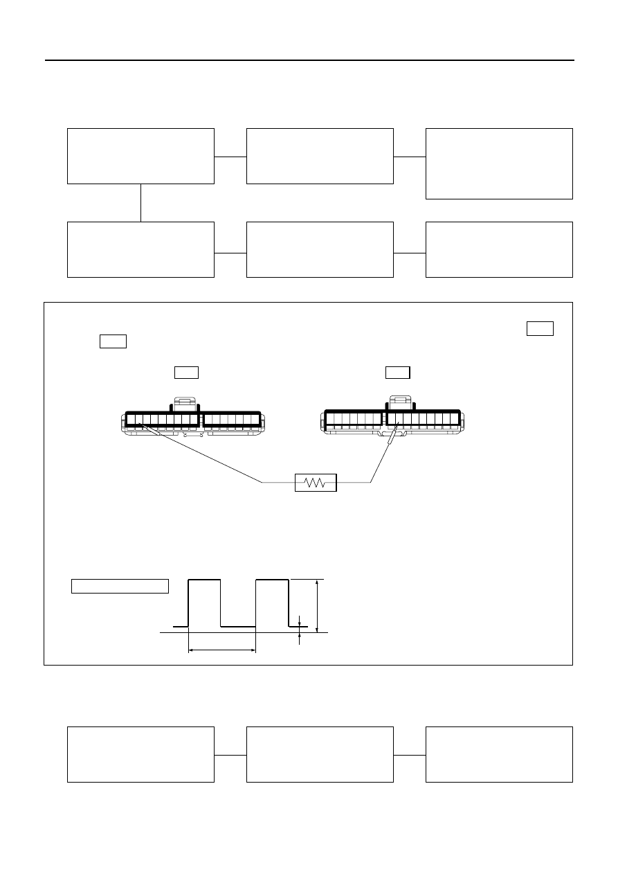
Inspection of a waveform by oscilloscope
1. Connect a resistance of 1.3 to 5k ohm (1.4W or more) between the harness side connectors 2 B-24
and 9 B-23 of the meter.
2.
2.
3.
Install a speedometer tester.
Turn on the starter SW.
Check the waveform at the time when the vehicle speed is at 60km/h.
Normal waveform
0V
23.6m sec.
2V or less
Approximate battery voltage - 2V
9
8
7
6
5
4
3
2
1
16
15
14
13
12
11
10
B-24
B-23
16
15
14
13
12
11
10
9
8
7
6
5
4
3
2
1
825RV108
Нет комментариевНе стесняйтесь поделиться с нами вашим ценным мнением.
Текст