Isuzu D-Max / Isuzu Rodeo (TFR/TFS). Manual — part 791
6A–44
ENGINE MECHANICAL (6VD1 3.2L)
Engine Assembly
Removal
060RW026
1. Disconnect battery ground and positive cable.
2. Remove battery.
3. Make alignment mark on the engine hood and hinges
before removal in order to return the hood to original
position exactly.
4. Remove engine hood.
5. Drain radiator coolant.
6. Disconnect accelerator cable and automatic cruise
control cable from throttle valve on common
chamber.
7. Remove the ECM.
D
Disconnect the two connectors from the ECM.
D
Remove fixing bolts on the common chamber.
D
Remove fixing bolts for ground cable.
8. Disconnect air duct with air cleaner cover.
9. Remove air cleaner assembly.
10. Disconnect canister vacuum hose.
11. Disconnect vacuum booster hose.
12. Disconnect three engine harness connectors.
13. Disconnect harness connector to transmission (left
front side of engine compartment), disconnect shift
on the fly harness connector from front side of front
axle and remove transmission harness bracket from
engine left side.
14. Disconnect ground cable between engine and frame.
15. Disconnect bonding cable connector on the back of
right dash panel.
16. Disconnect bonding cable terminal on the left bank.
17. Disconnect starter harness connector from starter.
18. Disconnect generator harness connector from
generator.
19. Disconnect coolant reserve tank hose from radiator.
20. Remove radiator upper and lower hoses.
21. Remove upper fan shroud.
22. Remove cooling fan assembly four fixing nuts, then
the cooling fan assembly.
23. Move drive belt tensioner to loose side using wrench
then remove drive belt.
24. Remove power steering pump fixing bolts, then
power steering pump. Place the power steering pump
along with piping on the body side.
25. Remove air conditioning compressor fixing bolts from
bracket and place the compressor along with piping
on the body side.
26. Remove four O
2
sensor harness connectors (two
each bank) from exhaust front pipe.
27. Remove three exhaust pipe fixing nuts from each
bank.
28. Remove two exhaust pipe fixing nuts from each
exhaust pipe, then move exhaust pipe to rear side of
vehicle.
29. Remove flywheel dust covers.
30. Disconnect two heater hoses from engine.
31. Disconnect fuel hose from right side of transmission.
CAUTION: Plug fuel pipe on engine side and fuel
hose from fuel tank.
32. Remove transmission assembly. Refer to
Transmission section in this manual.
33. Support the engine by engine hoist.
34. Remove two left side engine mount fixing bolts from
engine mount on chassis side.
35. Remove two right side engine mount fixing bolts from
engine mount on chassis side.
36. Remove engine assembly.

6A–45
ENGINE MECHANICAL (6VD1 3.2L)
Installation
CAUTION: When assembling the engine and
transmission, confirm that dowels have been
mounted in the specified positions at the engine
side. Also take care that dowel positions are different
between the manual transmission and the automatic
transmission.
Otherweise, the transmission may be damaged.
012RS009
1. Install engine assembly. Tighten engine mount fixing
bolts to frame to the specified torque.
Torque: 41 N·m (4.2 kg·m/30 lb ft)
2. Reconnect fuel hose to fuel pipe on engine.
3. Install transmission assembly. Refer to Transmission
section in this manual.
4. Reconnect two heater hoses to engine.
5. Install flywheel dust covers.
6. Install exhaust pipe and temporally tighten two (each
bank) rear exhaust flange nuts then tighten three stud
nuts (each bank) between exhaust manifold and
exhaust pipe, finally tighten rear side nuts to the
specified torque.
Torque:
Nuts: 43 N·m (4.4 kg·m/32 lb ft)
Stud nuts: 67 N·m (6.8 kg·m/49 lb ft)
060RW107
7. Reconnect O
2
sensor connector.
8. Install cooling fan assembly and tighten bolts/nuts to
the specified torque.
Torque : 22 N·m (2.2 kg·m/16 lb ft) for fan pulley
and fan bracket.
Torque : 10 N·m (1.0 kg·m/88.5 lb in) for fan and
clutch assembly.
9. Install air conditioner compressor to engine and
tighten to the specified torque.
6VD1
Torque : 43 N·m (4.4 kg·m/32 lb ft)
10. Install power steering pump, tighten fixing bolt to the
specified torque.
Torque :
M8 bolts : 22 N·m (2.2 kg·m/16 lb ft)
M10 bolts : 46 N·m (4.7 kg·m/34 lb ft)
6A–46
ENGINE MECHANICAL (6VD1 3.2L)
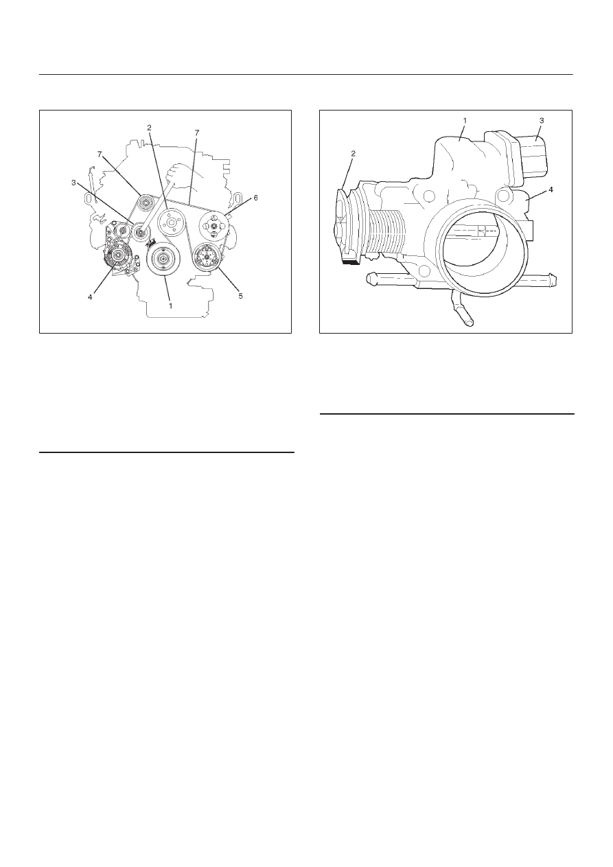
11. Move drive belt tensioner to loose side using wrench,
then install drive belt to normal position.
850RW001
Legend
(1) Crankshaft Pulley
(2) Cooling Fan Pulley
(3) Tensioner
(4) Generator
(5) Air Conditioner Compressor
(6) Power Steering Oil Pump
(7) Drive Belt
12. Install upper fan shroud.
13. Reconnect radiator upper and lower hoses.
14. Reconnect coolant reserve tank hose to radiator.
15. Reconnect generator harness connector.
16. Reconnect starter harness connector.
17. Reconnect bonding cable terminal on left bank
18. Reconnect bonding cable terminal on the back of right
dash panel.
19. Reconnect ground cable between engine and
chassis.
20. Reconnect harness connector to transmission and
install transmission harness bracket on engine left
side.
21. Reconnect three engine harness connectors.
22. Reconnect vacuum booster hose.
23. Reconnect canister vacuum hose.
24. Install air cleaner assembly.
25. Reconnect air duct.
26. Reconnect accelerator cable to throttle valve on
common chamber.
060RW083
Legend
(1) Throttle Valve Assembly
(2) Throttle Lever
(3) Idle Air Control Valve
(4) Throttle Position Sensor
27. Install the ECM.
D
Tighten the four bolts.
Torque : 10 N·m (1.0 kg·m/7 lb ft)
D
Connect the two connectors.
D
Tighten the two ground cable bolts.

6A–47
ENGINE MECHANICAL (6VD1 3.2L)
28. Install engine hood to the origine position.
D
Refer to installation procedure for Body section in
this manual.
D
Don’t need accelerator pedal cable adjustment.
D
Tighten the accelerator pedal cable nuts.
060RW093
Legend
(1) Lock Nut
(2) Nut
Нет комментариевНе стесняйтесь поделиться с нами вашим ценным мнением.
Текст