Isuzu D-Max / Isuzu Rodeo (TFR/TFS). Manual — part 1667

1-54 HEATING AND AIR CONDITIONING
CONTROL LEVER ASSEMBLY
REMOVAL AND INSTALLATION
Removal Steps
1. Instrument panel driver lower
2. Lower cluster assembly
3. Meter cluster assembly
4. Instrument panel lower center cover
assembly
5. Glove box
6. Knobs
▲
7. Heater bezel
▲
8. Fan control lever and / or A/C switch
connector
9. Control lever assembly
▲
10. Cables
cover assembly
Installation Steps
10. Cables
9. Control lever assembly
8. Fan control lever and / or A/C switch connector
7. Heater bezel
▲
6. Knobs
5. Glove box
4. Instrument panel lower center cover assembly
3. Meter cluster assembly
2. Lower cluster assembly
1. Instrument panel driver lower

HEATING AND AIR CONDITIONING 1-55
Important Operation - Removal
7. Heater Bezel
8. Fan and A/C Switch Connector
Pull the control lever assembly out and disconnect the
connectors.
10.Cables

1-56 HEATING AND AIR CONDITIONING
Important Operation - Installation
6. Control Lever Assembly
Adjust the control cables.
Air source control cable (Blower unit)
(1) Slide the control lever to the left.
(2) Connect the control cable at the "CIRC" position and fix it
with the clip.
Temperature control cable (Heater unit)
(1) Slide the control lever to the left.
(2) Connect the control cable at the "COLD" position and fix it
with the clip.
Air select control cable (Heater unit)
(1) Slide the control lever to the right.
(2) Connect the control cable at the "DEFROST" position and
fix it with the clip.
Check operation.
BEZEL
(AIR SELECTOR CABLE)
(TEMPERATURE CONTROL
CABLE)
(AIR SOURCE SELECT CABLE)
LHD
RHD
HEATING AND AIR CONDITIONING 1-57
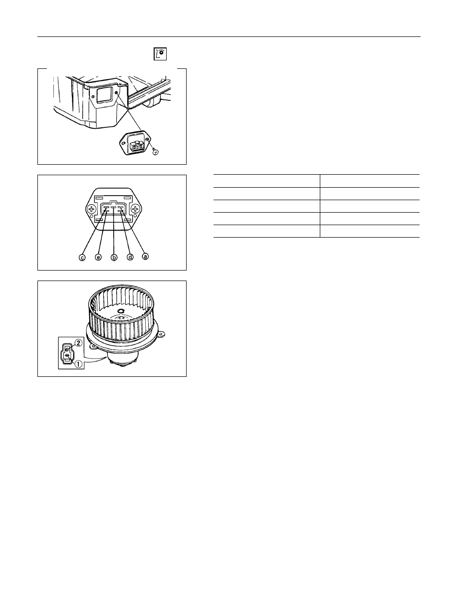
INSPECTION AND REPAIR
Resistor
As for air-conditioning model, fixed on right side of the
evaporator unit.
As for heater only model, fixed on right side of the duct placed
between blower unit and heater unit.
Replace the resistor with a new on if the coil is found to be
open or if the resistance value deviates from the specified
range.
Terminal
Resistance
a - b
2.40
Ω
b - d
0.90
Ω
b - e
0.28
Ω
b - c
-
Blower motor
Check blower motor for smooth rotation.
Connect the battery positive terminal to the No.1 (No.2: RHD)
terminal of the blower motor and negative to the No.2 (No.1:
RHD).
Be sure to check to see if the blower motor operates correctly.
Нет комментариевНе стесняйтесь поделиться с нами вашим ценным мнением.
Текст