Isuzu D-Max / Isuzu Rodeo (TFR/TFS). Manual — part 2009

FRONT SUSPENSION 3C-29
Important Operations
1. Bushing
Remover and Installer : 5-8840-0257-0
(J-29756)
3. Bolt, Nut and Washer
Tighten lower link nut finger-tight.
Perform the secure tightening after adjusting buffer clearance.
4. Lower End
Lower End Bolt Torque
N
⋅m (kgf⋅m/lb⋅ft)
68.7
± 6.9 (7.0 ± 0.7/50.6 ± 5.1)
5. Fulcrum Pin
Install the smaller clearance A to be inside and larger
clearance B outside of vehicle.
6 Bushing
Remover and Installer : 5-8840-0256-0
(J-29755)

3C-30 FRONT SUSPENSION
7. Plate and Nut
Tighten fulcrum pin nut finger-tight.
Perform the secure tightening after adjusting buffer clearance.
10.Bolt
Fulcrum Pin Bolt Torque
N
⋅m (kgf⋅m/lb⋅ft)
152.0
± 14.7 (15.5 ± 1.5/112.1 ± 10.8)
11.Upper End
Upper End Torque
N
⋅m (kgf⋅m/lb⋅ft)
32.4
± 2.9 (3.3 ± 0.3/23.9 ± 2.2)
13.14. 16. Nut
Knuckle Nut Torque
N
⋅m (kgf⋅m/lb⋅ft)
Lower End
147.1
± 9.8 (15.0 ± 1.0/108.5 ± 7.2)
Upper End
107.9
± 9.8 (10.0 ± 1.0/79.7 ± 7.2)
Steering Link End
107.9
± 9.8 (10.0 ± 1.0/79.7 ± 7.2)
Fasten the bushing nut, and keep the buffer clearance as
shown on the left diagram.
T = 53 mm (2.09 in)
Lower Link Nut
Lower Link Nut Torque
N
⋅m (kgf⋅m/lb⋅ft)
126.5
± 12.8 (12.9 ± 1.3/93.3 ± 9.4)
Upper Link Nut
Upper Link Nut Torque
N
⋅m (kgf⋅m/lb⋅ft)
107.9
± 14.7 (11.0 ± 1.5/79.6 ± 10.8)
FRONT SUSPENSION 3C-31
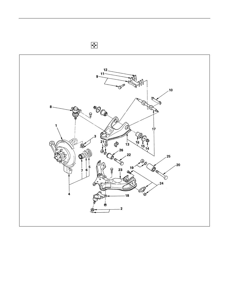
KNUCKLE, UPPER LINK AND LOWER LINK
(4
××××4 MODEL AND TFR25)
DISASSEMBLY
Disassembly Steps
Knuckle
1. Back plate and hub
2. Nut and cotter pin
3. Nut and cotter pin
4. Knuckle
5. Oil Seal (4
×4 model)
6. Washer (4
×4 model)
! 7. Needle bearing (4
×4 model)
Upper Link
8. Upper end
9. Bolt and plate
10. Nut Assembly
!11. Camber shims
!12. Caster shims
13. Upper link assembly
14. Nut
15. Plate
!16. Bushing
17. Fulcrum pin
Lower Link
18. Lower end
19. Nut and washer
20. Bolt
21. Nut and washer
22. Bolt
!23. Lower link assembly
24. Torsion bar arm
!25. Bushing
!26. Bushing

3C-32 FRONT SUSPENSION
Important Operations
7. Needle Bearing (4
××××4 model)
Remover : 5-8840-2000-0
(J-5822)
Sliding hammer : 5-8840-0019-0
(J-23907)
11.Camber Shims
12.Caster Shims
Note the positions and number of shims.
16.Bushing
Remover and installer : 5-8840-0256-0
(J-29755)
23.Lower Link Assembly
Before removal, remove the torsion bar, stabilizer bar and
shock absorber.
Brake hoses should be removed before disassembly and
installed after reassembly to avoid serious damage.
Нет комментариевНе стесняйтесь поделиться с нами вашим ценным мнением.
Текст