Isuzu D-Max / Isuzu Rodeo (TFR/TFS). Manual — part 612
ENGINE ELECTRICAL 6D – 55
Condition Cause
Circuit
Through glow plug
relay turns ON,
preheating is not
done.
Bad connection of FLW between battery and glow relay.
Bad connection or disconnection in preheating circuit of glow relay main contact
terminal connector.
Bad connection between plug connector and preheating circuit
1
9
Glow plug relay
turns ON, but does
not go OFF.
Bad timer.
Bad timer. Short circuiting in circuit or earth between 5 terminal and glow relay.
Bad glow relay.
6
Indication lamp is
not lit.
Bad timer.
Burning-out of light bulb.
8
Note: Circuit No. in rectangle is shown in the previous pre-heating chart.
2) Problems when the time water temperature of the engine is 0°C or above.
Condition Cause
Circuit
Indicator lamp is
not lit
Bad timer
Burning-out of bulb.
8
Turn glow relay
ON.
Bad thermoswitch or disconnection of thermo SW circuit.
(Indicator will light up for 3.5 seconds.)
Bad timer.
Bad timer. Short-circuiting in circuit or earth between terminal 5 and glow relay.
4
Note: Circuit No. in rectangle is shown in the previous pre-heating chart.
3) Burning-out of glow plug
When only one line is burned out, it has no effect on the start up of the engine. Even if one line is burned out,
judging from the characteristics of the glow plug, the impressed voltage will change only slightly. Therefore, no
judgment can be made by normal testing while the glow plug is installed. In order to check for disconnections
and burn-outs, the glow plugs will have to be removed from the connectors and checked one by one for
continuity.

6D – 56 ENGINE ELECTRICAL
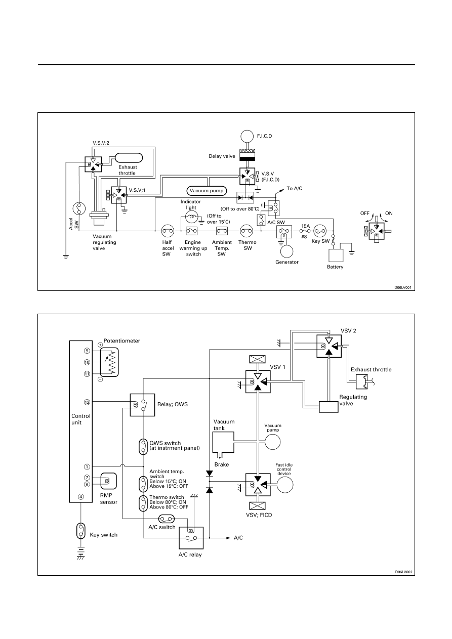
ENGINE WARMING-UP SYSTEM
GENERAL DESCRIPTION
The engine warm-up system is a device which changes the openning of the throttle valve for intake in accordance
with the engine rpm, controls the amount of the intake air, and changes the air ratio which is supplied to the cylinder.
The device is also provided with such functions as to measure the amount of heat capacity, to close the exhaust
throttle valve to raise the exhaust pressure, and to accelerate the rise in compression and temperature, and the
increase of fuel.
Operation of each device when warming-up switch is ON position.
Vacuum switching valve
Temp. sw.
Ambient sw.
Half sw. (only 4JA1)
Accel
sw.
1 2
FICD.
EXH.
valve
Intake
valve
FICD
One of above sw. OFF
-
OFF
OFF
OFF
Open
Open
NOT
Working
OFF ON OFF ON
Full
Close
Close
Working
All of above sw. ON
ON ON ON ON
Half
Close
Close
Working
ENGINE ELECTRICAL 6D – 57
ENGINE WARMING-UP SYSTEM CIRCUIT
Type A
Type B

6D – 58 ENGINE ELECTRICAL
TROUBLE SHOOTING
QUICK CHART FOR CHECK POINT
ENGINE WARMING-UP
When this system is out of order, checking as follows.
Switch
VSV Throttle
Checking parts
Trouble mode
Engine
warming up
Thermo
Ambient
temperature
Accel
Half Accel
(only 4JA1)
ENG. Warming
up Indicator
1
2
FICD
INT EXH
Cable
harness
The indicator light does not
light when switch is ON
position.
¡
¡
¡
¡
The system does not operate
¡
¡
¡
¡
¡
¡
¡ ¡ ¡ ¡
¡
Abbreviation
V.S.V. ; Vacuum switching valve
FICD ; Fast idle control device
INT ;
Intake
EX ;
Exhaust
Нет комментариевНе стесняйтесь поделиться с нами вашим ценным мнением.
Текст