Isuzu D-Max / Isuzu Rodeo (TFR/TFS). Manual — part 1849

7A2-12 DIAGNOSIS
F0: Diagnostic Trouble Code
F0: Read DTC Infor As Stored By ECU
F1: Clear DTC Information
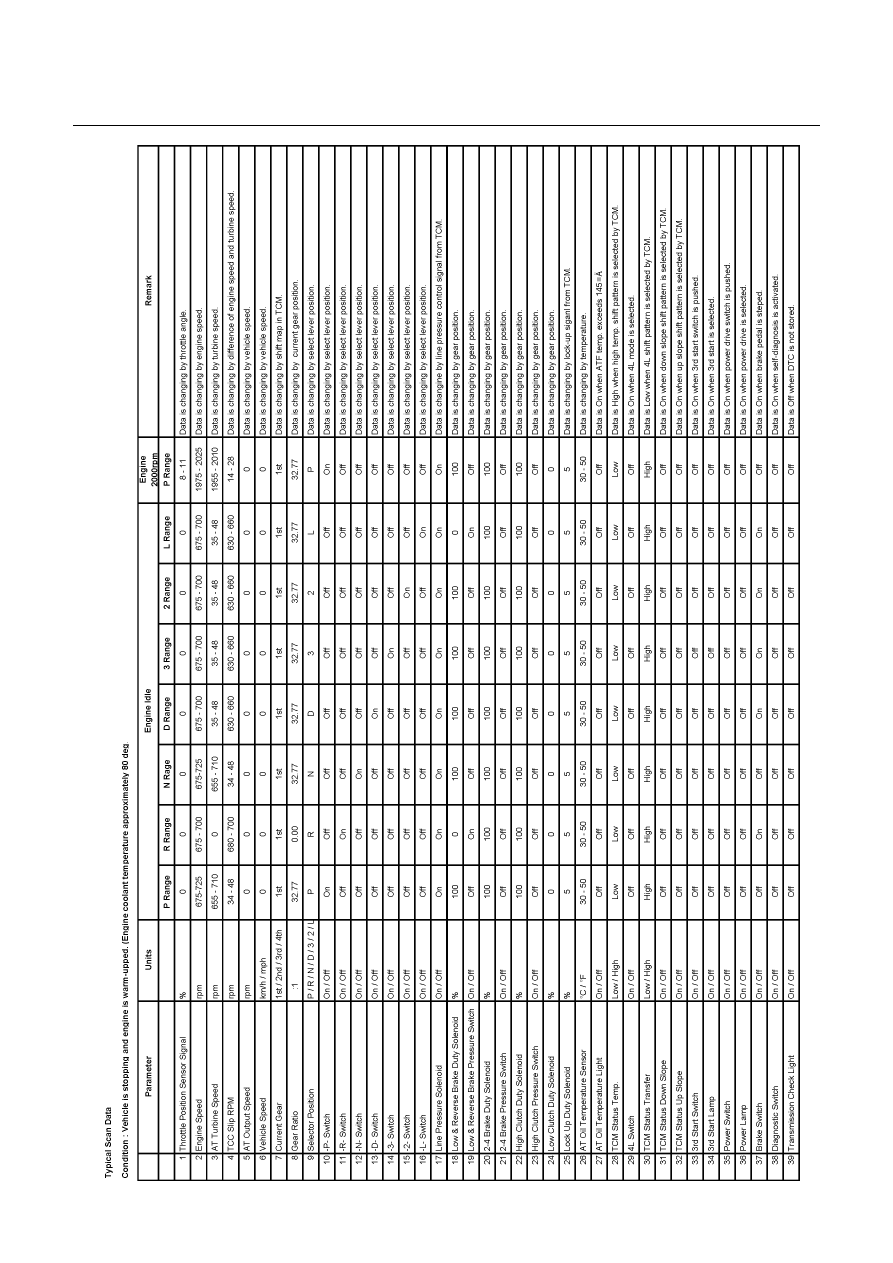
F1: Data Display
F2: Snapshot
F3: Miscellaneous Test
F0: Lamp
F0: Power Lamp Test
F1: 3rd Start Lamp Test
F2: AT Oil Temperature Lamp Test
F3: Transmission Check Light Test
F1: Solenoids
F0: Low & Reverse Brake Solenoid
F1: 2-4 Brake Solenoid
F2: High Clutch Solenoid
F3: Low Clutch Solenoid
F4: Line Pressure Solenoid
F5: Lock Up Duty Solenoid
F0: Diagnostic Trouble Code
The purpose of the "Diagnostic Trouble Codes" mode is
to display stored trouble code in the TCM.
When "Clear DTC Information" is selected, a "Clear DTC
Information", warning screen appears. This screen
informs you that by cleaning DTC's "all stored DTC
information in the TCM will be erased".
After clearing codes, confirm system operation by test
driving the vehicle.
F1: Data Display
The purpose of the "Data Display" mode is to continuously
monitor data parameters.
The current actual values of all important sensors and
signals in the system are display through F1mode.
See the "Typical Scan Data" section.
F2: Snapshot
"Snapshot" allows you to focus on making the condition
occur, rather than trying to view all of the data in
anticipation of the fault. The snapshot will collect
parameter information around a trigger point that you
select.
F3: Miscellaneous Test:
The purpose of "Miscellaneous Test" mode is to check for
correct operation of electronic system actuators.
DIAGNOSIS 7A2-13

7A2-14 DIAGNOSIS
Miscellaneous Test
The state of each circuit can be tested by using miscellaneous test menus. Especially when DTC cannot be
deteced, a faulty circuit can be diagnosed by testing each circuit by means of these menus.
Even DTC has been detected, the circuit tests using these menus could help discriminate between a mecanical
trouble and an electrical trouble.
Connect Tech 2 and select "Powertrain", "JR 405E" & "Miscellaneous Test".
F0: Lamps
The circuit is normal if the warning light in the meter panel comes on and goes out in accordance with Tech 2
instruction.
Lamps
F0: Power Lamp Test
F1: 3rd Start Lamp Test
F2: AT Oil Tempeature Lamp Test
F3: Transmission Check Light Test
F0: Power Lamp Test
Power Lamp Test
Power Lamp
Off
−
Press "Active" key.
Then, "POWER DRIVE" indicator lamp is turned on in the
meter panel.
−
Press "Inactive" key.
Then, "POWER DRIVE" indicator lamp is turned off in the
meter panel.
−
Press "Quit" Key to cancel the test.
F1: 3rd Start Lamp Test
F2: AT Oil Temperature Lamp Test
F3: Transmisstion Check Light Test
Test procedure is same as "F0: Power Lamp Test".
The circuit is normal if the warning light in the meter panel
comes on and goes out in accordance with Tech 2 instruction.
F1: Solenoids
The circuit is normal if clicking sound is generated in accordance with Tech 2 instruction.
Solenoids
F0: Low & Reverse Brake Solenoid
F1: 2-4 Brake Solenoid
F2: High Clutch Solenoid
F3: Low Clutch Solenoid
F4: Line Pressure Solenoid
F5: Lock Up Duty Solenoid

DIAGNOSIS 7A2-15
F0: Low & Reverse Brake Solenoid
Low & Reverse Brake Solenoid
Low & Reverse Brake Duty
0%
−
Press "Active" key.
Then, duty datio is indicated 100 % and "clicking sound" is
generated from the transmission control valve.
−
Press "Inactive" key.
Then, duty datio is indicated 0 % and "clicking sound" is
generated from the transmission control valve.
−
Press "Quit" Key to cancel the test.
F0: Low & Reverse Brake Solenoid
F1: 2-4 Brake Solenoid
F2: High Clutch Brake Solenoid
F3: Low Clutch Solenoid
F4: Line Pressure Solenoid
F5: Lock Up Duty Solenoid
Test procedure is same as "F0: Low & Revese Brake
Solenoid"
The circuit is normal if clicking sound is generated in
accordance with Tech 2 instruction.
Нет комментариевНе стесняйтесь поделиться с нами вашим ценным мнением.
Текст