Isuzu D-Max / Isuzu Rodeo (TFR/TFS). Manual — part 649

7A1–96 AUTOMATIC TRANSMISSION (4L30-E)
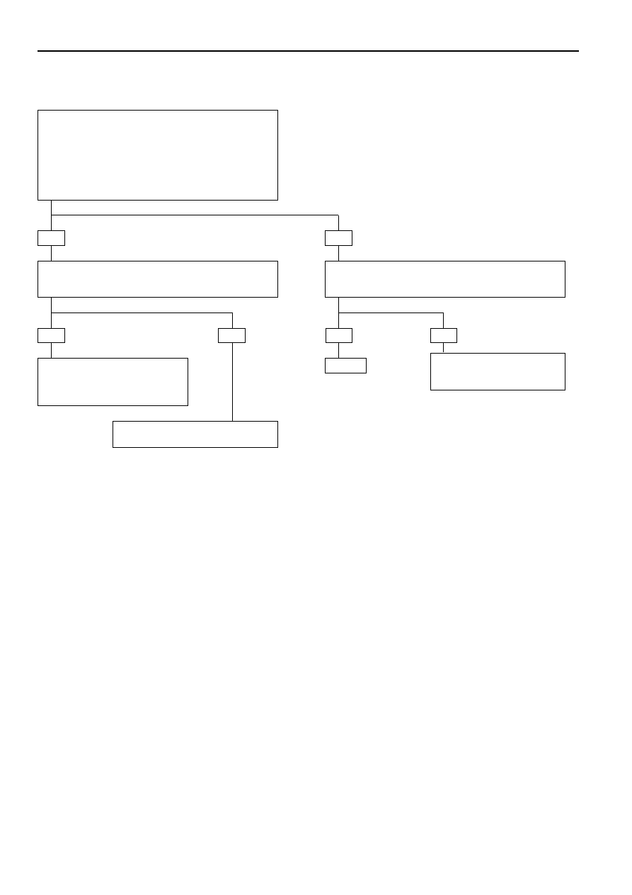
DIAGNOSTIC TROUBLE CODE (DTC) 35
FORCE MOTOR OPEN OR SHORT TO PLUS OR GROUND
This DTC flashes the CHECK TRANS indicator and
sets the BACKUP MODE.
Circuit Description:
•
The force motor solenoid is a device used to
regulate transmission line pressure. The TCM
uses TPS information and vehicle speed infor-
mation to determine the line pressure appro-
priate for a given load. The TCM will regulate the
pressure by applying a varying amperage to the
force motor solenoid. The applied amperage can
vary from 0.1 to 1.1 amp. The TCM then monitors
the amperage at the return line. If the return
amperage is more than 0.2 amp from the
commanded amperage, the DTC is stored.
•
The line pressure can vary from less than 50psi to
more than 200 psi. The line pressure varies
inversely to the amount of current. High current
causes low pressure and low current causes high
pressure.
Diagnostic Aids:
•
This Diagnostic is an electrical test done by the
TCM.
•
Detection conditions:
•
The TCM monitors the amperage at the return
line. When the return amperage is more than 0.2
amp from the commanded amperage, DTC is
stored.
•
Action after the detection time: BACKUP MODE
•
Recovery conditions: To recover, do an IGNITION
CYCLE.
FORCE
MOTOR
SOLENOID
CONTROL
(
+
)
TRANSMISSION
CONTROL
MODULE (TCM)
ECM MAIN RELAY
M-6
M-6
2(B)
1(E)
C-95
FORCE
MOTOR
SOLENOID
FORCE
MOTOR
SOLENOID
CONTROL
(—)
RED/GRN
RED/GRN
H-23
8
H-23
5
RED/BLK
BLK
BLK
BLK
7
H-25
C16(16)
C1(1)
D1(17)
C15(15)
GROUND
C-96
RED/BLU
RED/BLU
IGNITION
INPUT
A7(7)
AUTOMATIC
TRANSMISSION
RED/BLK
D07LW015

AUTOMATIC TRANSMISSION (4L30-E) 7A1–97
•
Ignition switch off.
•
Disconnect Transmission Control Module (TCM)
connector C-95 and C-96
•
Connect ohmmeter between connector C-95
terminals C15 and C16.
IF: Display is between 3.7 and 4.7 ohms:
•
Connect ohmmeter between connector C-95
terminals C15 and C1 (TCM ground) then between
terminal C15 and connecter C-96 terminal A7 (TCM
ignition) then between terminals C16 and C1 (TCM
ground) then between terminals C16 and A7 (TCM
ignition).
IF: Display indicates a short circuit:
•
Disconnect automatic transmission adapter case
connector M-6.
•
Connect ohmmeter between terminals 2(B) and 1(E)
of female half of the connector (solenoid side).
IF: Display between 3.7 and 4.7 ohms:
Repair wires for open between
terminals C15 or C16 and adapter
case connector.
Replace force motor solenoid.
Repair the short circuit.
The problem is
intermittent.
GOTO INTERMITTENT
CONDITIONS.
•
Disconnect solenoid connector.
•
Connect ohmmeter between solenoid
terminals.
IF: Display between 3.7 and 4.7 ohms:
Repair wires for open
between adapter case
connector and solenoid
connector.
YES
NO
YES
NO
DIAGNOSTIC TROUBLE CODE (DTC) 35
FORCE MOTOR OPEN OR SHORT TO PLUS OR GROUND
NO
YES
YES
NO

7A1–98 AUTOMATIC TRANSMISSION (4L30-E)
DIAGNOSTIC TROUBLE CODE (DTC) 36
SHIFT HIGH SHORT TO GROUND OR OPEN
This DTC flashes the CHECK TRANS indicator and
sets the BACKUP MODE.
Circuit Description:
•
The solenoids are activated by a current. This
current is produced by applying a voltage to one
side (the High side) and a ground to the other
side (Low side).
•
The High Side Driver (HSD) is a circuit of the
Transmission Control Module (TCM) that acts as
a switch between the solenoids and the supply
voltage. The High side of the solenoid is
permanently supplied with voltage, except in
BACKUP MODE or when Ignition is OFF the High
Side Driver is turned OFF.
•
The TCM continually monitors the solenoid
connection to its High Side Driver for either low
or high voltage.
•
There are two tests of the HSD: when the engine
is cranked (DTC82) and when the ignition is
turned ON (DTC36).
•
When the ignition is turned ON, and before the
engine is cranked, the TCM activates the shift
solenoids (A, B and Band) to check for short
circuits or open circuits. To do so the gear is set
to 4th, 3rd, 1st, 1st with band apply, 4th with no
HSD. Each one of the 5 tests requires 0.15
seconds. If the engine is cranked before the end
of all tests, the remaining tests are not done.
Diagnostic Aids:
•
This diagnostic is an electrical test done by the
TCM.
•
Detection conditions:
1 The solenoid High side connected to TCM
terminal C12 is shorted to ground or open.
2 The test is only done when ignition is ON.
3 Engine Speed < 480 RPM (not cranked) and
Output Speed = 0 RPM
4 The condition needs to be present for 0.15 to
0.75 second after ignition switch ON.
•
Action after the detection time: BACKUP MODE.
•
Recovery conditions: To recover, do an IGNITION
CYCLE.
TRANSMISSION
CONTROL
MODULE (TCM)
SHIFT
SOLENOID
A
SHIFT
SOLENOID
B
BAND
APPLY
SOLENOID
AUTOMATIC
TRANSMISSION
M-7
3(D)
4(C)
BRN/WHT
YEL/GRN
1(A)
BRN/BLK
H-23
H-23
16
6
13
YEL/BLK
YEL/BLK
2(B)
M-7
H-25
BLK
BLK
7
C12(12)
14
D1(17)
GROUND
C1(1)
A2(2)
A3(3)
A9(9)
C-96
C-95
GROUND
SHIFT &
BAND APPLY
SOLENOID
CONTROL
BLK
YEL/GRN
BRN/BLK
BRN/WHT
D07LW016
AUTOMATIC TRANSMISSION (4L30-E) 7A1–99
•
Connect ohmmeter between connector C-95 terminal
C12 and C1 (TCM ground).
IF: Short circuit:
•
Check for faulty connector or
wiring between terminal C12
and ground.
•
Repair.
The problem is intermittent.
GOTO INTERMITTENT CONDITIONS.
The problem is intermittent.
GOTO INTERMITTENT
CONDITIONS.
YES
YES
NO
DIAGNOSTIC TROUBLE CODE (DTC) 36
SHIFT HIGH SHORT TO GROUND OR OPEN
YES
NO
NO
•
Ignition switch off.
•
Disconnect Transmission Control Module (TCM)
connectors C-95 and C-96.
•
Connect ohmmeter between connector C-95 terminal
C12 and connector C-96 terminal A2 and between
C12 and A3 and between C12 and A9.
IF: Display is approx. 10 ohms for the band apply and 18
ohms for the other solenoids:
Repair.
•
Check for an open circuit between connector C-95
terminal C12 and the other terminals A2, A3 and A9.
IF: Wiring problem?
Нет комментариевНе стесняйтесь поделиться с нами вашим ценным мнением.
Текст