Isuzu D-Max / Isuzu Rodeo (TFR/TFS). Manual — part 86

4JA1-TC/4JH1-TC ENGINE DRIVEABILITY AND EMISSIONS
6E–339
ROUGH, UNSTABLE, OR INCORRECT IDLE, STALLING SYMPTOM
DEFINITIONS: Engine runs unevenly at idle. If severe,
the engine or vehicle may shake. Engine idle speed may
vary in RPM. Either condition may be severe enough to
stall the engine.
X
time
rpm
Rough Idle
Stall
Step
Action
Value(s)
Yes
No
1
Was the “On-Board Diagnostic (OBD) System Check”
performed?
—
Go to Step 2
Go to On Board
Diagnostic
(OBD) System
Check
2
1. Perform a bulletin search.
2. If a bulletin that addresses the symptom is found,
correct the condition as instructed in the bulletin.
Was a bulletin found that addresses the symptom?
—
Verify repair
Go to Step 3
3
Was a visually/physical check performed?
—
Go to Step 4
Go to Visual /
physical Check
4
Is the customer using the incorrect fuel type?
Diesel fuel
only
Replace with
diesel fuel
Go to Step 5
5
1. Check for incorrect idle speed. Ensure that the
following conditions are present.
• Engine fully warm.
• Accessories are “OFF”.
2. Using a Tech 2, monitor “Desired Engine Idle
Speed” and “Engine Speed”.
Is the “Engine Speed” within the specified values?
Desired
Engine Idle
Speed ± 25
rpm
Go to Step 7
Go to Step 6
6
Visually/physically inspect for the following conditions.
• Restrict air intake system. Check for a restricted air
filter element, or foreign objects blocking the air
intake system
• Check for objects blocking or excessive deposits in
the throttle bore and on the throttle plate
• Check for a condition that causes a large vacuum
leak, such as an incorrectly installed or faulty
crankcase ventilation hose.
• Restrict air intake system at the turbocharger.
Check for objects blocking the turbocharger
compressor wheel or turbine shaft sticking.
If a problem is found, repair as necessary.
Was a problem found?
—
Verify repair
Go to Step 7
7
Check the ECM & PSG grounds to verify that they are
clean and tight. Refer to the ECM wiring diagrams.
Was a problem found?
—
Verify repair
Go to Step 8

6E–340
4JA1-TC/4JH1-TC ENGINE DRIVEABILITY AND EMISSIONS
8
1. Using the Tech 2, ignition “On” and engine “Off”.
2. Monitor the “Neutral Switch” in the data display.
Does the Tech 2 indicate correct “Neutral Switch”
status depending on any shift positions?
If a problem is found, repair as necessary.
Was the problem found?
—
Verify repair
Go to Step 9
9
1. Using the Tech 2, ignition “On” and engine “Run”.
2. Monitor the “A/C Information Switch” in the data
display.
Does the Tech 2 indicate correct “A/C Information
Switch” status depending on A/C switch position?
If a problem is found, repair as necessary.
Was the problem found?
—
Verify repair
Go to Step 10
10
1. Using the Tech 2, display the ECT sensor and IAT
sensor value.
2. Check the displayed value.
Does the Tech 2 indicate correct temperature
depending on engine condition?
If a problem is found, repair as necessary.
Was the problem found?
—
Verify repair
Go to Step 11
11
1. Using the Tech 2, ignition “On” and engine “Run”.
2. Monitor the “Mass Air Flow” in the data display.
Does the Tech 2 indicate correct “Mass Air Flow”
depending on accelerator pedal operation?
—
Go to Step 16
Go to Step 12
12
Remove the MAF & IAT sensor assembly and check
for the following conditions.
• Objects blocking at the MAF sensor element.
If a problem is found, repair as necessary.
Was the problem found?
—
Verify repair
Go to Step 13
13
Check the MAF sensor harness for the following
conditions.
• Check for poor connector connection.
• Check for misrouted harness.
• Check for any accessory parts which may cause
electric interference.
If a problem is found, repair as necessary.
Was a problem found?
—
Verify repair
Go to Step 14
14
Substitute a known good MAF & IAT sensor assembly
and recheck.
Was the problem solved?
—
Go to Step 15
Go to Step 36
15
Replace the MAF & IAT sensor assembly.
Is the action complete?
—
Verify repair
—
16
1. Using the Tech 2, ignition “On” and engine “Off”.
2. Monitor the “Pedal/Throttle Position” and “Idle
Switch” in the data display.
Does the Tech 2 indicate correct “Pedal/Throttle
Position” from 0% to 100% and correct “Idle Switch”
status depending on accelerator pedal operation?
—
Go to Step 21
Go to Step 17
Step
Action
Value(s)
Yes
No

4JA1-TC/4JH1-TC ENGINE DRIVEABILITY AND EMISSIONS
6E–341
17
1. Using the Tech 2, ignition “On” and engine “Off”.
2. Monitor the “Pedal/Throttle Position” and “Idle
Switch” in the data display.
3. Adjust the accelerator cable or TPS within 0% to
100%.
Was the problem solved?
—
Verify repair
Go to Step 18
18
Check the TPS harness for the following conditions.
• Check for poor connector connection.
• Check for misrouted harness.
• Check for any accessory parts which may cause
electric interference.
If a problem is found, repair as necessary.
Was a problem found?
—
Verify repair
Go to Step 19
19
Substitute a known good TPS and recheck.
Was the problem solved?
—
Go to Step 20
Go to Step 36
20
Replace the TPS.
Is the action complete?
—
Verify repair
—
21
Remove the CKP sensor from the flywheel housing
and check for the following conditions.
• Objects sticking the CKP sensor.
• Objects sticking the CKP sensor pulser.
If a problem is found, repair as necessary.
Was the problem found?
—
Verify repair
Go to Step 22
22
Check the CKP sensor harness for the following
conditions.
• Check for poor connector connection.
• Check for misrouted harness.
• Check for any accessory parts which may cause
electric interference.
If a problem is found, repair as necessary.
Was a problem found?
—
Verify repair
Go to Step 23
23
Substitute a known good CKP sensor and recheck.
Was the problem solved?
—
Go to Step 24
Go to Step 25
24
Replace the CKP sensor.
Is the action complete?
—
Verify repair
—
Step
Action
Value(s)
Yes
No
6E–342
4JA1-TC/4JH1-TC ENGINE DRIVEABILITY AND EMISSIONS
25
1. Using the Tech 2 and ignition “On” and engine
“Run”.
2. Monitor the following parameters in the data
display.
• “Desired Injection Quantity” & “Injection Quantity”
• “Desired Injection Start” & “Actual Injection Start”
Are the large gap or unstable parameter displayed
between “Desired” and “Actual”?
—
Go to Step 29
Go to Step 26
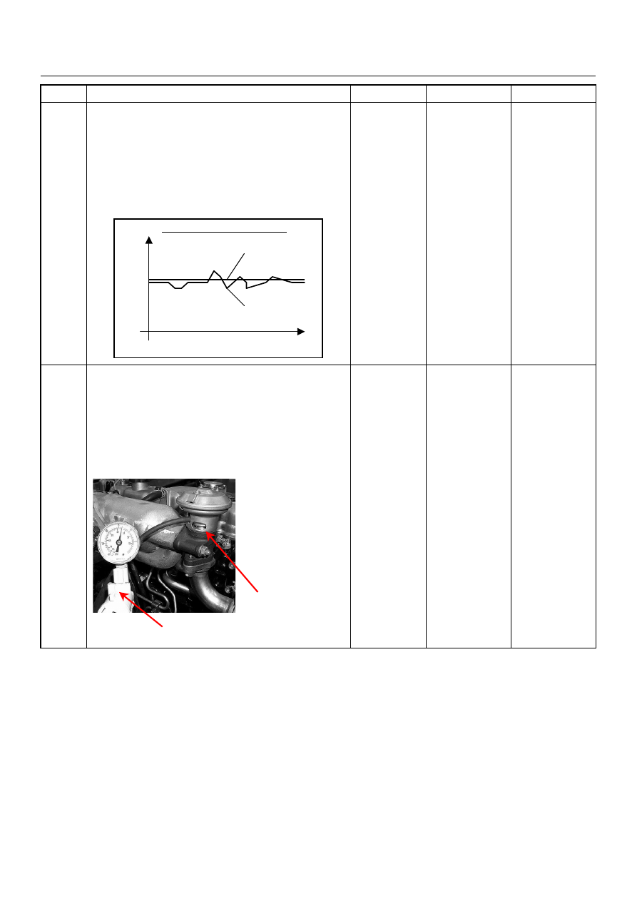
26
Using the vacuum pump and check the EGR valve (if
equipped) operation for the following condition through
the small window.
• Restrict shaft movement. Check for objects sticking
the shaft, broken diaphragm or excessive carbon
deposit.
If a problem is found, repair as necessary.
Was a problem found?
—
Verify repair
Go to Step 27
Step
Action
Value(s)
Yes
No
When idling or part-throttle
High
Desired
Low
Time
Actual
Vacuum Pump
Small Window
Нет комментариевНе стесняйтесь поделиться с нами вашим ценным мнением.
Текст