Isuzu D-Max / Isuzu Rodeo (TFR/TFS). Manual — part 213

ENGINE DRIVEABILITY AND EMISSIONS
6E–93
5
1. Set the Injector Adapter Cable to injector #1.
2. Press the “Push to Start Test” button on the fuel
injector tester.
3. Observe the voltage reading on the DVM.
Important: The voltage reading may rise during the
test.
4. Record the lowest voltage observed after the first
second of the test.
5. Set the Injector Adapter Cable to the next injector
and repeat steps 2, 3, and 4.
Did any fuel injector have an erratic voltage reading
(large fluctuations in voltage that did not stabilize) or a
voltage reading above the specified value?
9.5V
Go to Step 4
Go to Step 6
6
1. Identify the highest voltage reading recorded
(other than those above 9.5V).
2. Subtract the voltage reading of each injector from
the highest voltage selected in step 1. Repeat until
you have a subtracted value for each injector.
For any injector, is the subtracted value in step 2
greater than the specified value?
0.6V
Go to Step 4
Go to Step 7
7
Caution: In order to reduce the risk of fire and
personal injury, wrap a shop towel around the fuel
pressure connection. The towel will absorb any
fuel leakage that occurs during the connection of
the fuel pressure gauge. Place the Towel in an
approved container when the connection of the
fuel pressure gauge is complete.
1. Connect the 5-8840-0378-0 Fuel Pressure Gauge
to the fuel pressure test port.
2. Energize the fuel pump using the Scan Tool.
3. Place the bleed hose of the fuel pressure gauge
into an approved gasoline container.
4. Bleed the air out of the fuel pressure gauge.
5. With the fuel pump running, observe the reading
on the fuel pressure gauge.
Is the fuel pressure within the specified values?
296kPa-
376kPa
(43-55psi)
Go to Step 8
Go to Fuel
System
Diagnosis
8
Turn the fuel pump OFF.
Does the fuel pressure remain constant?
—
Go to Step 9
Go to Fuel
System
Diagnosis
Step
Action
Value(s)
Yes
No

6E–94
ENGINE DRIVEABILITY AND EMISSIONS
9
1. Connect the 5-8840-0378-0 Fuel Injector Tester
and 5-8840-2589-0 Injector Adapter Cable to the
fuel injector harness connector.
2. Set the amperage supply selector switch on the
fuel injector tester to the “Balance Test” 0.5-2.5
amp position.
3. Using the Scan Tool turn the fuel pump ON then
OFF in order to pressurize the fuel system.
4. Record the fuel pressure indicated by the fuel
pressure gauge after the fuel pressure stabilizes.
This is the first pressure reading.
5. Energize the fuel injector by depressing the “Push
to Start Test” button on the fuel injector tester.
6. Record the fuel pressure indicated by the fuel
pressure gauge after the fuel pressure gauge
needle has stopped moving. This is the second
pressure reading.
7. Repeat steps 1 through 6 for each fuel injector.
8. Subtract the second pressure reading from the
first pressure reading for one fuel injector. The
result is the pressure drop value.
9. Obtain a pressure drop value for each fuel injector.
10. Add all of the individual pressure drop values.
This is the total pressure drop.
11. Divide the total pressure drop by the number of
fuel injectors. This is the average pressure drop.
Does any fuel injector have a pressure drop value that
is either higher than the average pressure drop or
lower than the average pressure drop by the specified
value?
10kPa
(1.5psi)
Go to Step 10
Go to OBD
System Check
10
Re-test any fuel injector that does not meet the
specification. Refer to the procedure in Step 11.
NOTE: Do not repeat any portion of this test before
running the engine in order to prevent the engine from
flooding.
Does any fuel injector still have a pressure drop value
that is either higher than the average pressure drop or
lower than the average pressure drop by the specified
value?
10kPa
(1.5psi)
Go to Step 11
Go to
Symptoms
11
1. Replace the faulty fuel injector(s). Refer to Fuel
Injector.
2. Disconnect the 5-8840-2589-0 Injector Adapter
Cable for F/I check and re-connect the original F/I
check connector.
Is the action complete?
—
Verify repair
—
Step
Action
Value(s)
Yes
No
ENGINE DRIVEABILITY AND EMISSIONS
6E–95
FUEL SYSTEM ELECTRICAL TEST
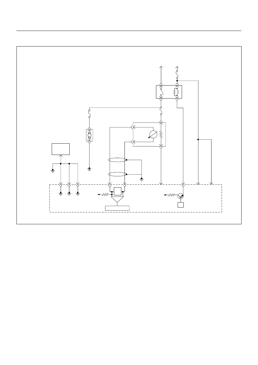
Circuit Description
When the ignition switch is first turned ON, the engine
control module (ECM) energizes the fuel pump relay
which applies power to the in-tank fuel pump. The fuel
pump relay will remain ON as long as the engine is
running or cranking and the ECM is receiving 58X
crankshaft position pulses. If no 58X crankshaft position
pulses are present, the ECM de-energizes the fuel
pump relay within 2 seconds after the ignition is turned
ON or the engine is stopped.
The fuel pump delivers fuel to the fuel rail and injectors,
then to the fuel pressure regulator. The fuel pressure
regulator controls fuel pressure by allowing excess fuel
to be returned to the fuel tank. With the engine stopped
and ignition ON, the fuel pump can be turned ON by
using a command by the scan tool.
Diagnostic Aids
An intermittent may be caused by a poor connection,
rubbed-through wire insulation, or a wire broken inside
the insulation. Check for the following items:
• Poor connection or damaged harness - Inspect the
ECM harness and connectors for improper mating,
broken locks, improperly formed or damaged
terminals, poor terminal-to-wire connection, and
damaged harness.
Caution: To reduce the risk of fire and personal
injury:
• It is necessary to relieve fuel system pressure
before connecting a fuel pressure gauge.
Refer to Fuel Pressure Relief Procedure,
below.
• A small amount of fuel may be released when
disconnecting the fuel lines. Cover fuel line
fittings with a shop towel before
disconnecting, to catch any fuel that may leak
out. Place the towel in an approved container
when the disconnect is completed.
µP
V
Ign
-
+
Crankshaft
Position
Sensor
J1-1 J1-2 J1-17
Battery
Voltage
Battery
Voltage
2.0
WHT
ECM
10A
450
mV
A/D Converter
Vcc
+5V
-
+
TIMING
COVER
J2-6
J2-21
Fuel
Pump
FUEL
PUMP
20A
2.0
BLK
2.0
BLK/
BLU
Fuel
Pump
Relay
O
2
SENSOR
10A
Heated
O
2
Sensor
0.85
RED/
WHT
0.5
GRN/
WHT
0.5
RED/
WHT
0.5
BLU/
WHT
0.5
BLU
0.5 PNK
J2-31
J2-11
J2-2
J2-18
M
Engine
Control
Module
(ECM)
6E–96
ENGINE DRIVEABILITY AND EMISSIONS
Fuel Pressure Relief Procedure
1. Remove the fuel cap.
2. Remove the fuel pump relay from the underhood
relay center.
3. Start the engine and alow it to stall.
4. Crank the engine for an additional 3 seconds.
Fuel Pressure Gauge Installation
1. Remove the fuel pressure fitting cap.
2. Install fuel pressure gauge 5-8840-0378-0 to the
fuel feed line located in front of and above the right
side valve cover.
3. Reinstall the fuel pump relay.
Fuel System Electrical Test
Step
Action
Value(s)
Yes
No
1
Was the “On-Board Diagnostic (OBD) System Check”
performed?
—
Go to Step 2
Go to On Board
Diagnostic
(OBD) System
Check
2
1. Using the Tech 2, ignition “On” and engine “On”.
2. Select the “Miscellaneous Test” and perform the
“Fuel Pump Relay” in the “Relays”.
3. Operate the Tech 2 in accordance with procedure.
Was the fuel pump operated, when the Tech 2 is
operated?
—
Go to Fuel
System
Diagnosis
Go to Step 3
3
Check the “Fuel Pump” fuse (20A).
If the fuse is burnt out, repair as necessary.
Was the problem found?
—
Verify repair
Go to Step 4
4
Check for poor/faulty connection at the fuel pump, fuel
pump relay or ECM connector. If a poor/faulty
connection is found, repair as necessary.
Was the problem found?
—
Verify repair
Go to Step 5
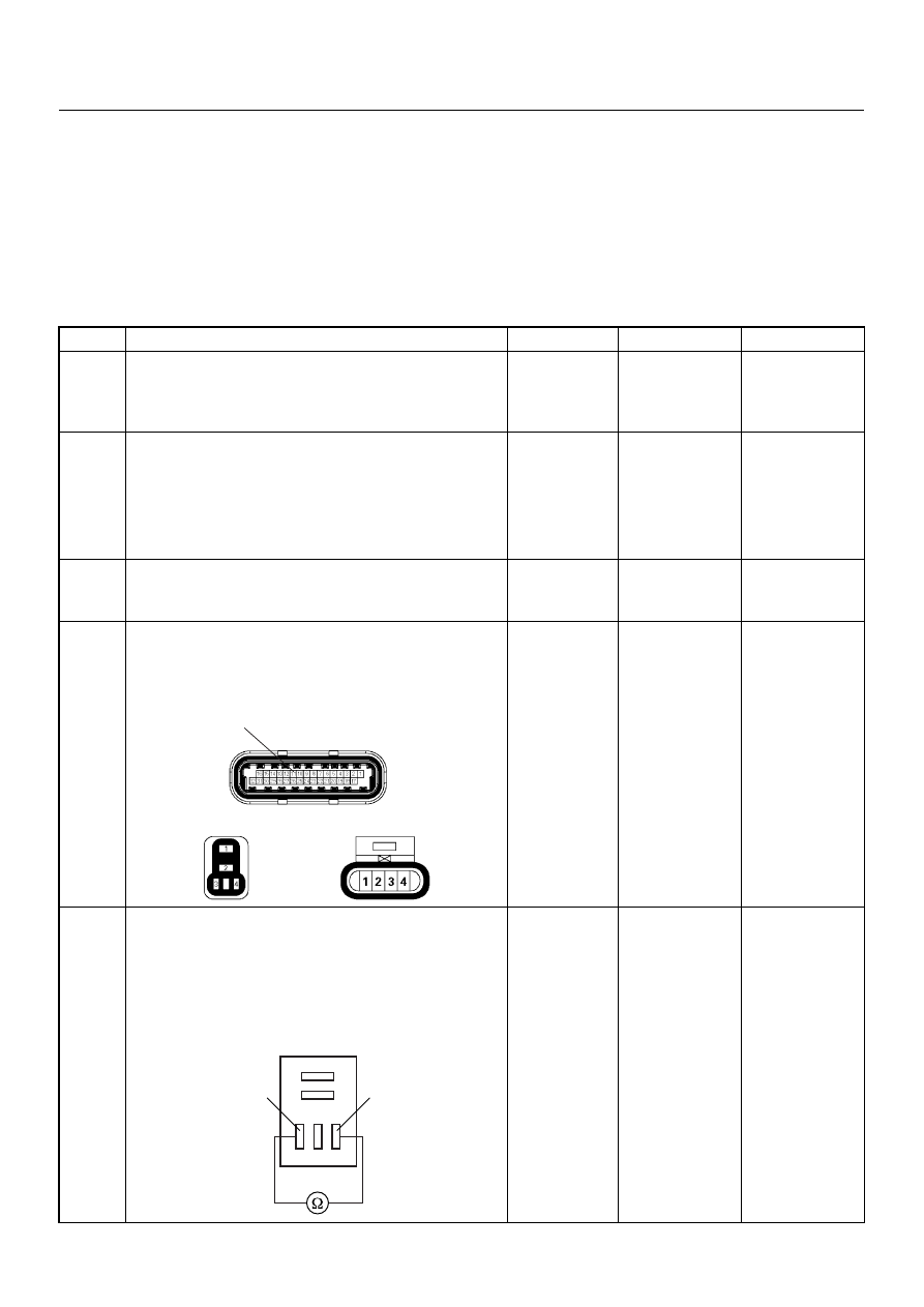
5
Using the DVM and check the fuel pump relay.
1. Ignition “Off”, engine “Off”.
2. Remove the fuel pump relay from the relay box.
3. Check the relay coil.
Was the DVM indicated specified value?
Continuity
Go to Step 6
Replace fuel
pump relay and
verify repair
11
C56(J2)
F2
X2
Fuel Pump Relay
3
4
Нет комментариевНе стесняйтесь поделиться с нами вашим ценным мнением.
Текст