Isuzu D-Max / Isuzu Rodeo (TFR/TFS). Manual — part 851
6E–133
3.2L ENGINE DRIVEABILITY AND EMISSIONS
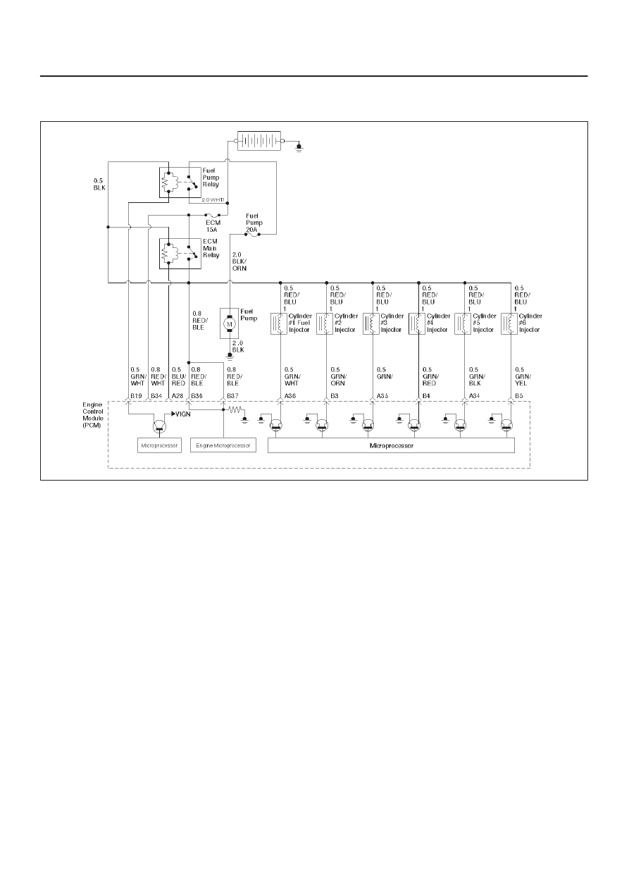
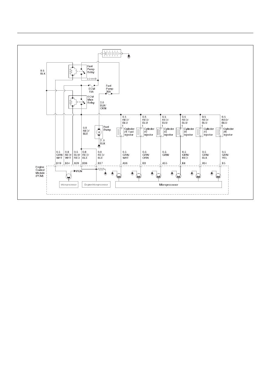
Diagnostic Trouble Code (DTC) P0202 (Flash DTC=31) Injector 2 Control
Circuit
060RW055
Circuit Description
The Engine Control Module ECM has six individual
injector driver circuits. Each controls an injector. When a
driver circuit is grounded by the ECM, the injector is
activated. The ECM monitors the current in each driver
circuit. The voltage on each driver is monitored to detect
a fault. If the voltage is not what the ECM expects to
monitor on the circuit, a DTC is set. This DTC is also set if
an injector driver is shorted to voltage or if there is an open
circuit.
Conditions for Setting the DTC
D
The battery voltage is more than 11 volts.
D
Injector pulse reading is between 2.5m second and
7.5m second.
D
No fuel cut.
D
Engine running speed is between 700 r.p.m and 2000
r.p.m.
D
No related CKP/CMP DTCs.
D
No injector pulse reading with engine running speed is
200 r.p.m.
Action Taken When the DTC Sets
D
The ECM will illuminate the malfunction indicator lamp
(MIL) the first time the fault is detected.
D
The ECM will store conditions which were present
when the DTC was set as Freeze Frame and in the
Failure Records data.
Conditions for Clearing the MIL/DTC
D
The ECM will turn “OFF” the MIL on the third
consecutive trip cycle in which the diagnostic has been
run and the fault is no longer present.
D
A history DTC P0202 will clear after 40 consecutive
warm-up cycles occur without a fault.
D
DTC P0202 can be cleared by using the Tech 2 “Clear
Info” function or by disconnecting the ECM battery
feed.
Diagnostic Aids
An injector driver circuit that is open or shorted to voltage
will cause a DTC P0202 to set. It will also cause a misfire
due to an inoperative injector. A misfire DTC will also be
set indicating which cylinder is inoperative.
Long term and short term fuel trims that are excessively
high or low are a good indication that an injector is faulty.
Use Fuel Injector Coil Test Procedure to check for faulty
injectors.
6E–134 3.2L ENGINE DRIVEABILITY AND EMISSIONS
Test Description
The number(s) below refer to the step number(s) on the
Diagnostic Chart.
3. This step determines if DTC P0202 is the result of a
hard failure or an intermittent condition.
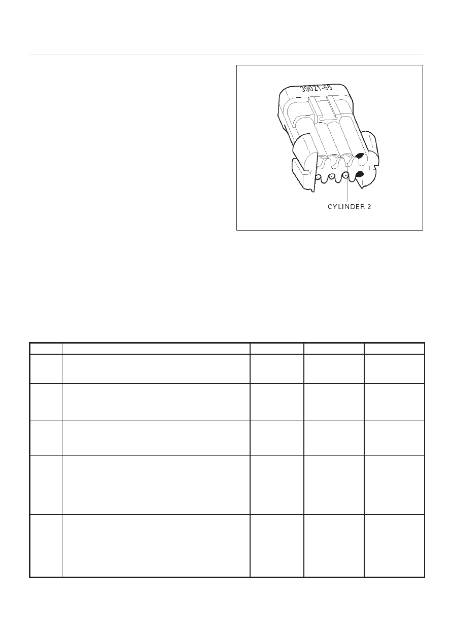
5. A special injector test connector is provided so that
the injectors can be electrically tested without
removal of the manifold. The special 7-way gray
connector is located at the rear of the air cleaner
assembly. The test connector can be identified by
the blue connector lock which is tethered to the
wiring harness. If the light for cylinder 2 is “ON”
steady before cranking the engine as well as while
cranking the engine, then the injector driver circuit is
shorted to ground.
If the test light blinks while cranking, the ECM and
the wiring to the injectors are OK. Fuel Injector Coil
Test Procedure will check if the injectors are faulty.
R321055
7. Because the test light was “ON” steady, voltage to
the injector is OK, but the driver circuit is grounded
at all times. This step determines if the circuit is
shorted to ground or the ECM is faulty.
9.The reading should be about 12-14
W
.
10.Locating the open in the harness or in the injector
will require removal of the manifold to provide
access.
DTC P0202 – Injector 2 Control Circuit
Step
Action
Value(s)
Yes
No
1
Was the “On-Board Diagnostic (OBD) System Check”
performed?
—
Go to
Step 2
Go to
OBD
System
Check
2
Will the engine start?
—
Go to
Step 3
Go to
Engine
Cranks But
Will Not Run
chart
3
1. Install the Tech 2. Clear the DTC.
2. Idle the engine for one minute.
Does DTC P0202 reset?
—
Go to
Step 5
Go to
Step 4
4
1. Review the Freeze Frame data with the ignition
“ON” and the engine “OFF” and note the
parameters.
2. Operate the vehicle within the Freeze Frame
conditions as noted.
Does P0202 reset?
—
Go to
Step 5
Go to
Diagnostic
Aids
5
1. Engine “OFF.”
2. Disconnect the injector test connector.
3. Install an injector test light 5-8840-2636-0 on
injector test connector
4. Crank the engine and note the light.
Does the cylinder 2 test light blink?
—
Go to
Fuel
Injector Coil
Test
Procedure
Go to
Step 6

6E–135
3.2L ENGINE DRIVEABILITY AND EMISSIONS
DTC P0202 – Injector 2 Control Circuit
(Cont'd)
Step
No
Yes
Value(s)
Action
6
Note whether the injector test light for cylinder 2 was
“OFF” or “ON” steady in step 5.
Was the test light “ON” steady while cranking the
engine?
—
Go to
Step 7
Go to
Step 9
7
1. Disconnect the ECM connector for the affected
injectors.
2. With a test light connected to B+, probe the affected
injector driver circuit.
Does the test light illuminate?
—
Go to
Step 8
Go to
Step 15
8
Repair short to ground in the injector driver circuit.
Is the action complete?
—
Go to
OBD
System
Check
—
9
1. Disconnect the injector test connector.
2. At the injector side of the harness, connect an
ohmmeter between the positive wire (red with blue
tracer) and the wire for cylinder 2 (green with orange
tracer).
Does the ohmmeter indicate continuity?
—
Go to
Step 11
Go to
Step 10
10
Repair the open injector harness wire or open injector.
Is the action complete?
—
Verify repair
—
11
At the ECM side of the injector test connector, check
the green/orange wire for a short to voltage.
Was there a short to voltage?
—
Go to
Step 12
Go to
Step 13
12
Repair the short to voltage.
Is the action complete?
—
Verify repair
—
13
Check for an open circuit between the injector test
connector and the ECM.
Was there an open circuit?
—
Go to
Step 14
Go to
Step 15
14
Repair the open circuit.
Is the action complete?
—
Verify repair
—
15
Replace the ECM.
Is the action complete?
—
Verify repair
—
6E–136 3.2L ENGINE DRIVEABILITY AND EMISSIONS
Diagnostic Trouble Code (DTC) P0203 Injector 3 Control Circuit
060RW055
Circuit Description
The Engine Control Module ECM has six individual
injector driver circuits. Each controls an injector. When
the driver circuit is grounded by the ECM, the injector is
activated. The ECM monitors the current in each driver
circuit. The voltage on each driver is monitored to detect
a fault. If the voltage is not what the ECM expects to
monitor on the circuit, a DTC is set. This DTC is also set if
an injector driver is shorted to voltage or if there is an open
circuit.
Conditions for Setting the DTC
D
The battery voltage is more than 11 volts.
D
Injector pulse reading is between 2.5m second and
7.5m second.
D
No fuel cut.
D
Engine running speed is between 700 r.p.m and 2000
r.p.m.
D
No related CKP/CMP DTCs.
D
No injector pulse reading with engine running speed is
200 r.p.m.
Action Taken When the DTC Sets
D
The ECM will illuminate the malfunction indicator lamp
(MIL) the first time the fault is detected.
D
The ECM will store conditions which were present
when the DTC was set as Freeze Frame and in the
Failure Records data.
Conditions for Clearing the MIL/DTC
D
The ECM will turn “OFF” the MIL on the third
consecutive trip cycle in which the diagnostic has been
run and the fault is no longer present.
D
A history DTC P0203 will clear after 40 consecutive
warm-up cycles occur without a fault.
D
DTC P0203 can be cleared by using the Tech 2 “Clear
Info” function or by disconnecting the ECM battery
feed.
Diagnostic Aids
An injector driver circuit that is open or shorted to voltage
will cause a DTC P0203 to set. It will also cause a misfire
due to an inoperative injector. A misfire DTC will also be
set indicating which cylinder is inoperative.
Long term and short term fuel trims that are excessively
high or low are a good indication that an injector is faulty.
Use Fuel Injector Coil Test Procedure to check for faulty
injectors.
Нет комментариевНе стесняйтесь поделиться с нами вашим ценным мнением.
Текст