Isuzu D-Max / Isuzu Rodeo (TFR/TFS). Manual — part 1829
MSG MODEL (4WD) 7B-93
Important Operations
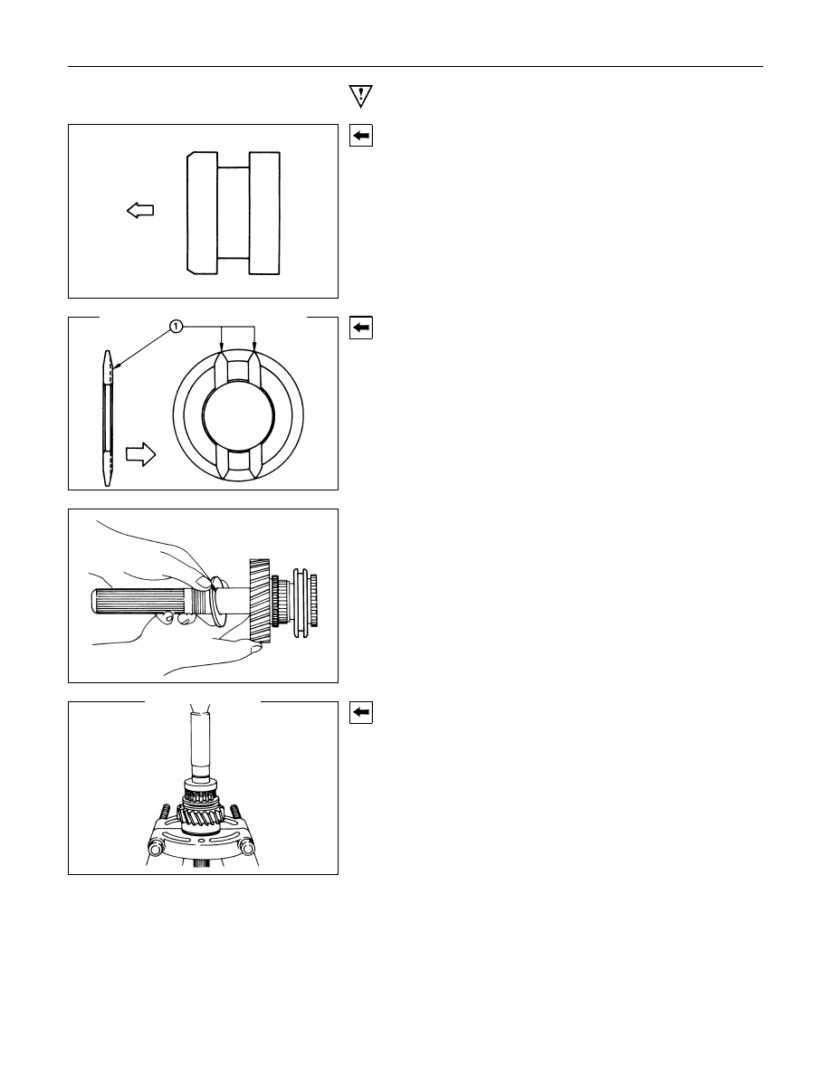
1. 4
××××2/4××××4 sleeve
Install the 4
×2/4×4 sleeve the output shaft.
The chamfered side of the sleeve facing the output shaft gear.
4. Thrust Washer
Install the thrust washer to the output shaft.
The oil grooved side of the washer facing the output shaft gear.
5. Ball Bearing
Use a bench press to install the ball bearing to the output shaft.
The snap ring grooved side of the bearing turned to the
speedometer drive gear.
7B-94 MSG MODEL (4WD)
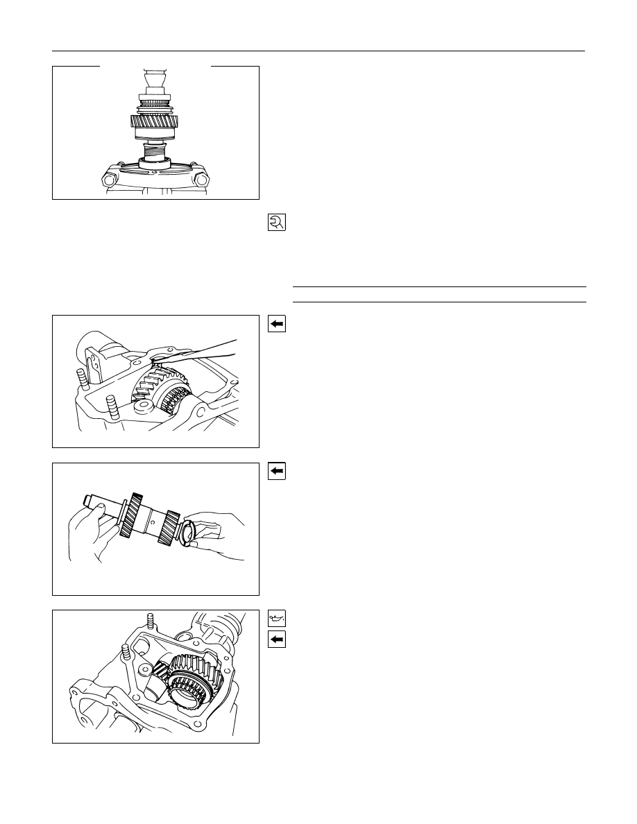
9. Ball bearing
Use a bench press to install the ball bearing to the output shaft.
The shield side of the bearing must be facing to the nut.
10.Nut
1) Install the nut to the output shaft.
2) Tighten the nut to the specified torque.
Nut Hex. : 41 mm (1-5/8 in)
Output Shaft Nut Torque
N
⋅m(kgf⋅m/lb⋅ft)
127.4
± 9.8 (13 ± 1 / 94.0 ± 7.2)
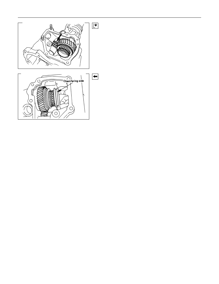
11.Output Shaft Assembly
1) Install the bearing snap ring to the transfer case snap ring
groove.
2) Place the output shaft assembly to the transfer case bore.
3) Use a pair of snap ring pliers to expand the snap ring.
4) Move the output shaft assembly to fit the snap ring to the
bearing.
16.Thrust Washer
Install the thrust washer to the counter shaft.
The thrust washer oil grooved side must be facing the counter
gear.
17.O-Ring
18.Counter Shaft Assembly
1) Apply new engine oil to the O-ring.
2) Position the counter shaft slot for the thrust washer tang at
twelve o'clock.
3) Make sure the both of washer tangs positions at twelve
o'clock.
4) Install the output shaft assembly to the transfer case bore.
MSG MODEL (4WD) 7B-95
Check to make sure the thrust washer tangs align with the
mating slots properly.
19.High/Low Sleeve
Install the High/Low sleeve to the output shaft.
The chamfered side of the sleeve must be facing the adaptor
case.
21.Distance plate
22.Lock Plate
Semi-tighten the lock plate bolts.
Before tighten the lock plate bolts, must be done the counter
gear clearance adjustment.
Note:
Refer to transfer case assembly installation procedures on
major components in this section.
7B-96 MSG MODEL (4WD)
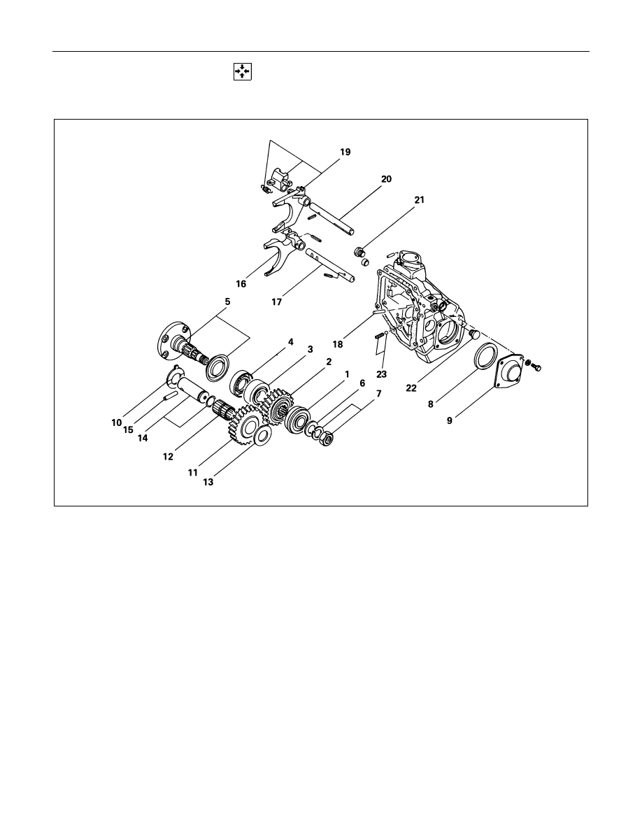
MINOR COMPONENT
TRANSFER SIDE CASE ASSEMBLY
Reassembly Steps
! 1. Ball bearing
! 2. Front output shaft gear
! 3. Ball bearing
! 4. Oil seal
! 5. Front output shaft
6. Thrust washer
7. Nut and lock washer
8. Distance piece
! 9. Front output shaft cover
!10. Thrust washer
11. Idler gear
12. Needle bearing
!13. Thrust washer
!14. Idler gear shaft
!15. Dowel pin
!16. High/Low shift arm
!17. High/Low shift rod
18. Interlock pin
!19. 4
×2/4×4 Shift arm and shift block
!20. 4
×2/4×4 Shift rod
!21. Screw plug
!22. Screw plug
23. Detent spring and ball
Нет комментариевНе стесняйтесь поделиться с нами вашим ценным мнением.
Текст