Isuzu D-Max / Isuzu Rodeo (TFR/TFS). Manual — part 641
7A1–64 AUTOMATIC TRANSMISSION (4L30-E)
CHART 3: TRANSMISSION AND TCM IDENTIFICATION
Chart 3 contains a list of all important information concerning rear axle ratio, Transmission Control Module
(TCM), and transmission identification.
VEHICLE
TCM TRANSMISSION
Type
Engine
ISUZU Parts No.
Calibration
Isuzu Part No.
Model Code
Code
Isuzu/
3.2L V6
4.555
TFR
8-09350-909-0
G22
8-96018-434-0
FV (4X2)
Rr axle
Ratio
A
B
E
C
D
F
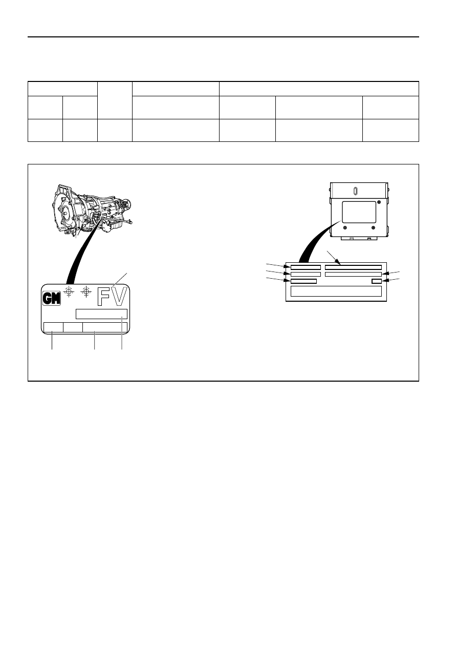
The idenification plate is
located on the left-hand side
of the transmission above the
mode switch.
AT Transmission identification on
vehicle identification plate :
1. Model code
2. Calibration code
3. Production serial number
4. Production part number
TCM IDENTIFICATION:
A. ISUZU part number
B. Model of car
C. DELCO part number
D. Application
E. Service TCM number
F. Broadcast code
G 22
96
0000 000
018 434
PART No.
SERIAL No.
SAL
HYDRAMATIC
STRASBOURG
MADE IN FRANCE
1
2
3
4
F07LW001

AUTOMATIC TRANSMISSION (4L30-E) 7A1–65
CHART 5: F5: ACTUATOR TEST QUICK CHECK
Before carrying out the Actuator Test, the selector lever should be placed in selector position ”N“.
The ignition should be switched ON, engine not running.
FOR
TECH2 DISPLAY
NOTES
CORRECT RESULT
DIAGNOSIS
SEE
1
SOLENOID A
Press arrow up (ON)
“Click” heard from
DTC 31
Press arrow down (OFF)
transmission
or 41
SOLENOID B
Press arrow up (ON)
“Click” heard from
DTC 32
Press arrow down (OFF)
transmission
or 42
SHIFT SOLENOID
Press arrow up (ON)
“Click” heard from
DTC 82
Press arrow down (OFF)
transmission
TCC SOLENOID
Not used
–
–
TCC HIGH (D)
Press arrow up (ON)
“Click” heard from
DTC 33
Press arrow down (OFF)
transmission
or 43
POWER LAMP
Press arrow up (ON)
POWER lamp ON
TRANSMISSION
Press arrow down (OFF)
OPERATING
MODE TEST
(PAGE 133)
CHK. TRN. LAMP
Press arrow up (ON)
CHECK TRANS lamp
CHECK TRANS
Press arrow down (OFF)
ON
CHECK (PAGE 50)
1
FOR DIAGNOSIS OF A DTC SEE CHART 2: DIAGNOSTIC TROUBLE CODES (DTC) (PAGE 63)
7A1–66 AUTOMATIC TRANSMISSION (4L30-E)
DIAGNOSTIC TROUBLE CODE (DTC) 11
OUTPUT SPEED FAILURE
This DTC flashes the CHECK TRANS indicator and
sets the BACKUP MODE.
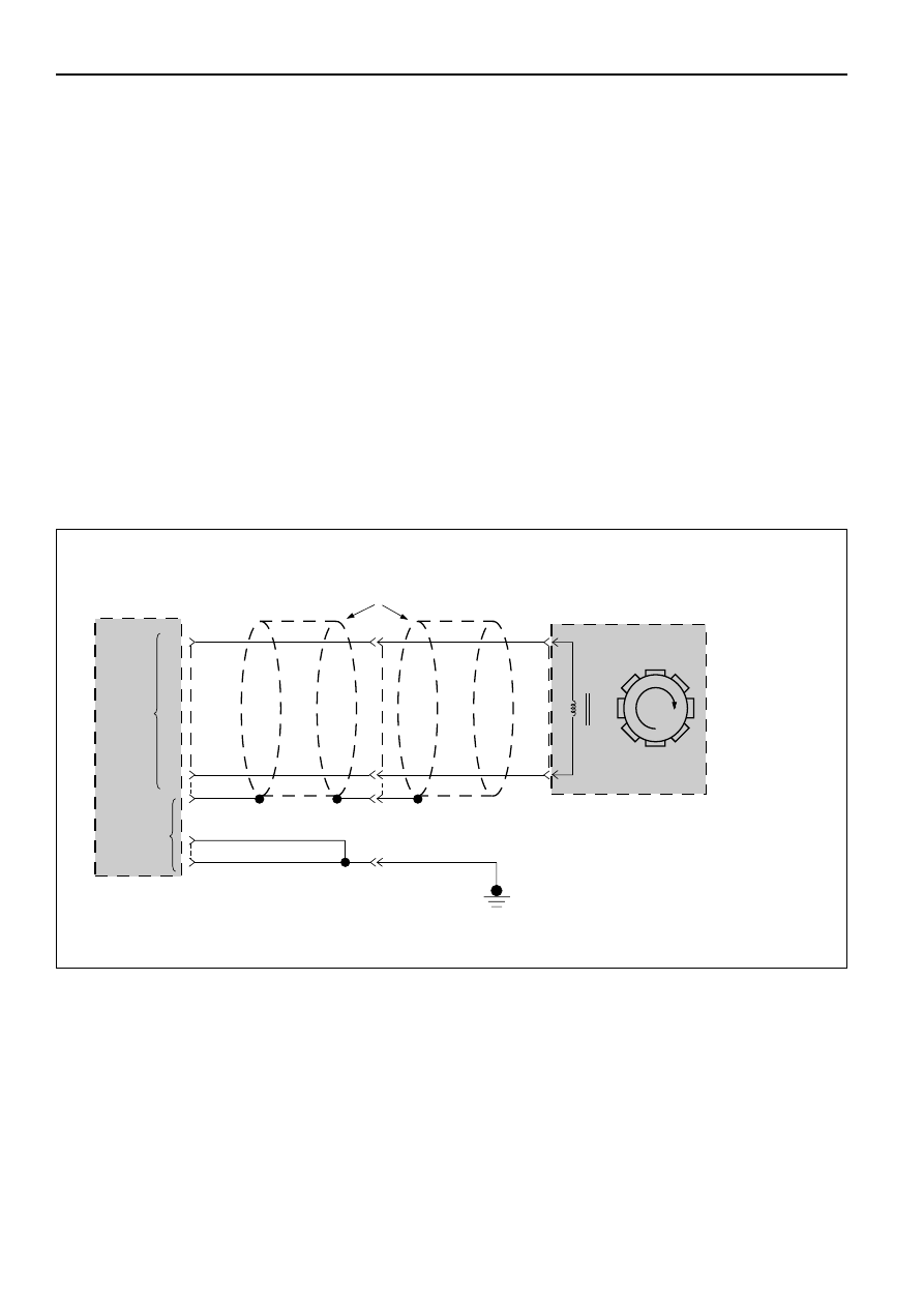
Circuit Description:
The transmission output speed sensor provides
information on vehicle speed to the Transmission
Control Module (TCM). The speed sensor circuit
consists of a magnetic induction type sensor. The
sensor is mounted above a target wheel pressed on
the output shaft in the transmission extension. As
the output shaft turns, the target wheel teeth induce
a variable voltage in the magnetic pickup. This
alternating current (AC) signal is provided to the
TCM. The voltage increases with the speed of the
wheel but this is not used to define the speed of the
vehicle. As the vehicle moves faster, the signal
alternates faster between positive and negative
voltages. The Output speed information is
proportional to the frequency of the signal.
Diagnostic Aids:
•
This diagnostic is not an electrical test done by
the TCM but a test between different information
(“logic test”).
•
Detection conditions:
1 Output Speed < or = 0 RPM.
2 Engine Speed > 3000 RPM.
3 No Malfunction: Engine Speed DTC 13. Mode
Switch DTC54.
4 Selector lever not in Park, Reverse, or Neutral.
5 The conditions need to be present for at least
5 seconds.
•
Action after the detection time:
1 CHECK TRANS Indicator is turned ON.
2 TCM in BACKUP MODE
•
Recovery conditions : To recover do an IGNITION
CYCLE.
TRANSMISSION
CONTROL
MODULE (TCM)
TRANSMISSION
SPEED SENSOR
A12(12)
C-96
C-95
C1(1)
D1(17)
1
M-15
2
TRANSMISSION SPEED
SENSOR SHIELDS
+
—
OUTPUT
SPEED
INPUT
H-23
10
11
9
PNK
B11(23)
B12(24)
GROUND
BLK
BLK
7
H-25
PNK
BLU
BLK
BLU
D07LW006
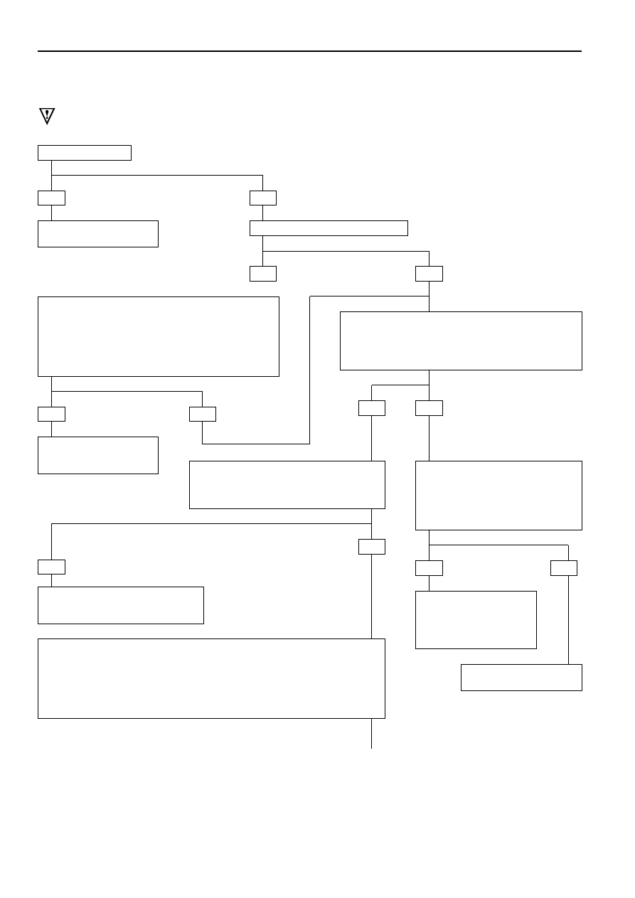
IF the DTC 53 is set:
GOTHROUGH DTC 53 first
and do a test drive.
Problem is intermittent.
GOTO INTERMITTENT
CONDITIONS.
Check for faulty TCM connection.
IF OK GOTO TCM MEM-CAL
REPLACEMENT.
YES
YES
YES
NO
NO
NO
IF you have a SCAN TOOL: TECH2?
•
Raise drive wheels.
•
Connect the TECH2 GOTHROUGH TECH2
CONNECTION.
•
Push “F0”: DATALIST: DISPLAY. Read “AT OUTPUT
SPEED”.
IF: Output Speed different from 0 RPM when the wheels
are turning:
•
Ignition switch OFF.
•
Disconnect TCM connector C-95 and C-96.
•
Connect ohmmeter between connector C-96 terminal
A12 and terminal B12.
IF: display is approx. 3K ohms:
•
Connect ohmmeter between connector
C-96 terminal A12 and ground connector
C-95 terminal C1.
IF: display indicates an open circuit:
Replace transmission
speed sensor.
NO
YES
NO
YES
NO
YES
•
Disconnect transmission speed
sensor connector M-15.
•
Connect ohmmeter between
terminals 1 and 2 of the speed
sensor.
IF: display approx. 3K ohms:
•
Wires from Connector
C-96 to sensor
connector are open or
shorted together.
•
Repair.
HINT: the wire between TCM terminal B12 and sensor connector M-15 terminal 2
can be shorted to ground or open without creating a problem because the TCM
B12 pin is connected to the TCM ground internally and the signal is detected only
on the A12 input.
•
Check wire for a short to ground between terminal A12 and sensor connector
M-15 terminal 1.
IF: display indicates a short circuit:
AUTOMATIC TRANSMISSION (4L30-E) 7A1–67
DIAGNOSTIC TROUBLE CODE (DTC) 11
OUTPUT SPEED FAILURE
CAUTION:
If wire to connector C-96 terminal B12 is short to voltage, Transmission Control Module
(TCM) will be damaged.
A
CONTINUED
ON NEXT PAGE
Нет комментариевНе стесняйтесь поделиться с нами вашим ценным мнением.
Текст