Isuzu D-Max / Isuzu Rodeo (TFR/TFS). Manual — part 324
AUTOMATIC TRANSMISSION (AW30-40LE) 7A-145
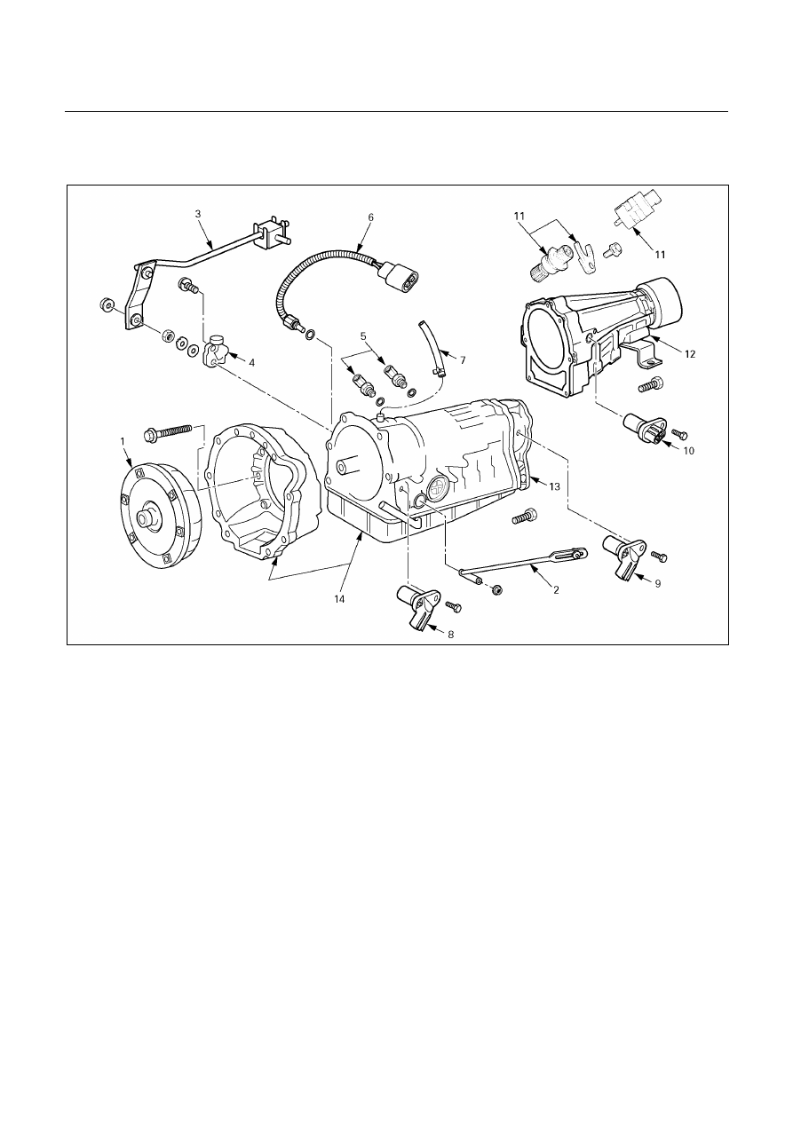
DISASSEMBLY OF MAJOR
COMPONENTS (1)
240R200036
Disassembly steps
1. Torque converter
2. Transmission control rod and select
lever (UBS and TFR/S)
3. Transmission control rod and select
lever (’01 TFR)
4. Neutral start switch
5. Elbow
6. Oil temperature sensor
7. Breather hose
8. Input revolution sensor
9. Output revolution sensor (4×4)
10. Output revolution sensor (4×2)
11. Speedometer sensor, speedometer
driven gear and plate (4
× 2)
12. Extension housing (4
× 2)
13. Adapter housing (4
× 4)
14. Transmission assembly
7A-146 AUTOMATIC TRANSMISSION (AW30-40LE)
Disassembly steps
1. Torque
converter
2. Transmission control rod and select lever (UBS and
TFR/S)
3. Transmission control rod and select lever (’01 TFR)
249RW003
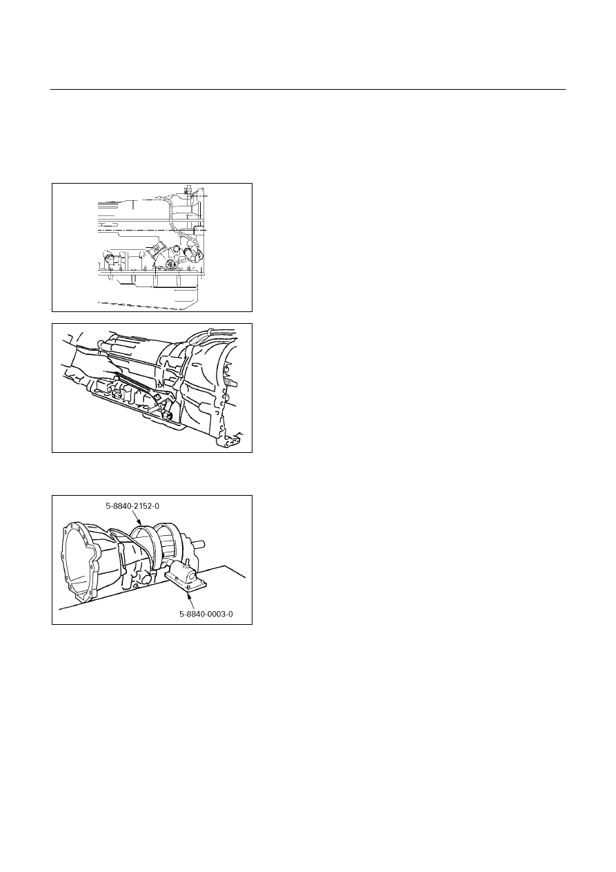
4. Neutral start switch
Unstake the lock washer.
Remove the nut and bolts, and then remove the neutral
start switch.
Remove the lock washer and grommet.
240RY00001
5. Elbow
Remove two elbows from transmission case.
6. Oil temperature sensor
7. Breather hose
8. Input revolution sensor
9. Output revolution sensor (4×
×
×
×4)
10. Output revolution sensor (4×
×
×
×2)
11. Speedometer sensor, speedometer driven gear and
plate (4
×××× 2)
12. Extension housing (4
×××× 2)
13. Adapter housing (4
×××× 4)
240R200021
14. Transmission assembly
Install special tool to the transmission unit.
Holding fixture: 5-8840-2152-0 (J-37227)
Holding fixture base: 5-8840-0003-0 (J-3289-20)
AUTOMATIC TRANSMISSION (AW30-40LE) 7A-147
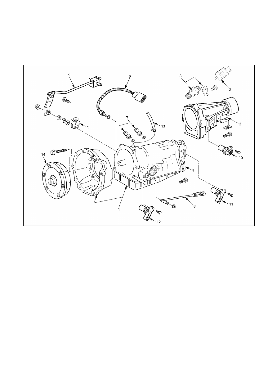
REASSEMBLY OF MAJOR
COMPONENTS (1)
240R200035
Reassembly steps
1. Transmission
assembly
2. Extension housing (4×2)
3. Speedometer driven gear, plate, and
speedometer sensor (4×2)
4. Adapter housing (4×4)
5. Neutral start switch
6. Oil
temperature
sensor
7. Elbow
8. Transmission control rod and select
lever (UBS and TFR/S)
9. Transmission control rod and select
lever (’01 TFR)
10. Output revolution sensor (4×2)
11. Output revolution sensor (4×4)
12. Input revolution sensor
13. Breather hose
14. Torque converter
Reassembly steps
1. Transmission assembly
2. Extension housing (4×
×
×
×2)
Install a new gasket and the extension housing to the
transmission case.
Torque: 36 N・・・・m (3.7 kg・・・・m/27 Ib・・・・ft)
7A-148 AUTOMATIC TRANSMISSION (AW30-40LE)
3. Speedometer driven gear, plate, and speedometer
sensor (4×
×
×
×2)
Torque:
Plate bolt – 15 N・・・・m (1.5 kg・・・・m/11 Ib・・・・ft)
Speedometer sensor – 25 N・・・・m (2.5 kg・・・・m/18 Ib・・・・ft)
241RY00020
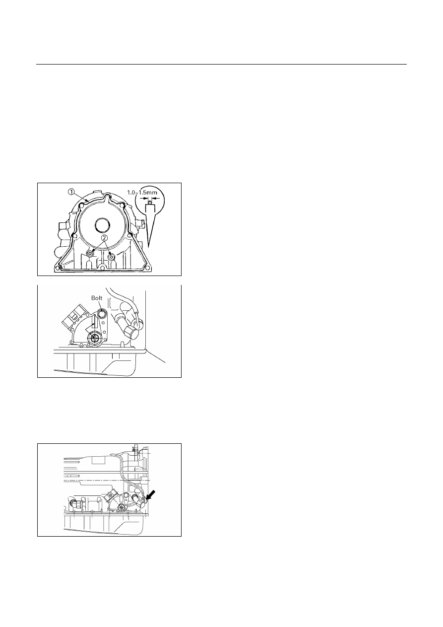
4. Adapter housing (4×
×
×
×4)
Remove any gasket material on the contacting surfaces
of the adapter housing and transmission case.
Apply liquid gasket (TB1281-B or its equivalent) (1) and
install the apply gaskets (2) to the adapter housing as
shown in the figure.
Install the adapter housing to the transmission case.
Torque: 34 N・・・・m (3.5 kg・・・・m/25 Ib・・・・ft)
249L100003
5. Neutral start switch
Using the transmission select lever, fully turn the
manual valve lever shaft back and return two notches.
It is now in neutral.
Insert the neutral start switch onto the manual valve
lever shaft and temporarily tighten the adjusting bolt.
Install the lock washer and nut.
Torque: 7 N・・・・m (0.7 kg・・・・m/61 Ib・・・・in)
Align the neutral standard line and the switch groove
and tighten the adjusting bolt.
Torque: 13 N・・・・m (1.3 kg・・・・m/113 Ib・・・・in)
Bend the tabs of the lock washer.
NOTE:
Bend at least two of the lock washer tabs.
249L100001
6. Oil temperature sensor
Install the oil temperature sensor to the transmission
case.
Torque: 15 N・・・・m (1.5 kg・・・・m/11 Ib・・・・ft)
Нет комментариевНе стесняйтесь поделиться с нами вашим ценным мнением.
Текст