Isuzu D-Max / Isuzu Rodeo (TFR/TFS). Manual — part 1241
ELECTRICAL-BODY AND CHASSIS 8-303
INSPECTION AND REPAIR
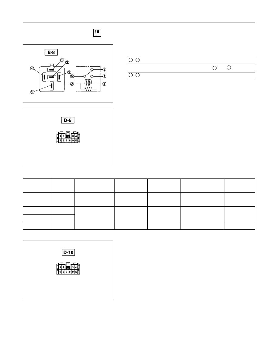
Power Window Relay
Check continuity between the relay terminals.
1
-
5
. . . . . . .No continuity
(When battery voltage is applied between
2
and
4
)
1
-
5
. . . . . . .Continuity
Harness side
Driver Seat Side Power Window & Door Lock
Switch
1. Harness Side Connector Circuit
Disconnect the switch connector, and check voltage and
continuity between the harness side connector terminals as
shown in the following table.
Terminal
No.
Wire
color
Connecting to
Check item
Connectin
g terminal
Check condition
Standard
2 G/R
Power window
relay
Voltage
2-Ground
Starter SW “ON”
Approx.
12V
1 L/R
Power window
10 L/W
motor
5 B
Ground Continuity
5-Ground - Continuity
Harness side
Front Passenger’s Power Window & Door Lock
Switch
1. Harness Side Connector Circuit
Disconnect the switch connector, and check voltage and
continuity between the harness side connector terminals as
shown in the following table.
Continuity
-
1-10
Continuity
8-304 ELECTRICAL-BODY AND CHASSIS
Terminal
No.
Wire
color
Connecting to
Check item
Connectin
g terminal
Check condition
Standard
9 G/R
Power window
relay
Voltage
9-Ground
Starter SW “ON”
Approx.
12V
6 L/R
Power window
10 L/W
motor
5 B
Ground Continuity
5-Ground
- Continuity
Harness side
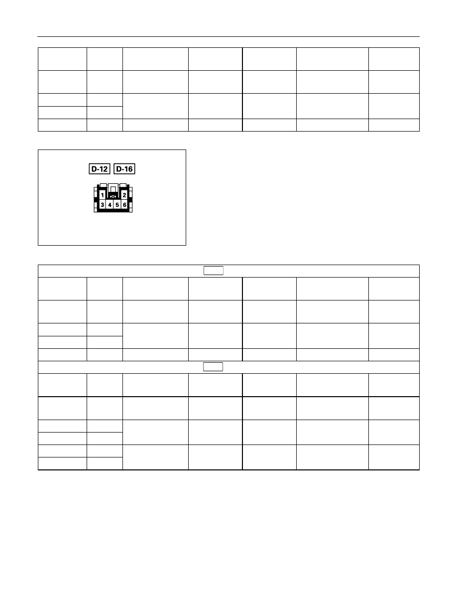
Rear Power Window Switch-LH & RH
1. Harness Side Connector Circuit
Disconnect the switch connector, and check voltage and
continuity between the harness side connector terminals as
shown in the following tables.
D-12
(RR-LH)
Terminal
No.
Wire
color
Connecting to
Check item
Connectin
g terminal
Check condition
Standard
4 G/R
Power window
relay
Voltage
4-Ground
Starter SW “ON”
Approx.
12V
5 L/R
Power window
6 BR/W
motor
3 B
Ground Continuity
3-Ground
- Continuity
D-16
(RR-RH)
Terminal
No.
Wire
color
Connecting to
Check item
Connectin
g terminal
Check condition
Standard
4 G/R
Power window
relay
Voltage
4-Ground
Starter SW “ON”
Approx.
12V
5 L/R
Power window
6 BR/W
motor
3 B
1 B
Continuity
-
6-10
Continuity
Continuity
Continuity
6-10
-
Continuity
Continuity
6-10
-
Ground Continuity
3-1
Continuity
-

ELECTRICAL-BODY AND CHASSIS 8-305
Harness side
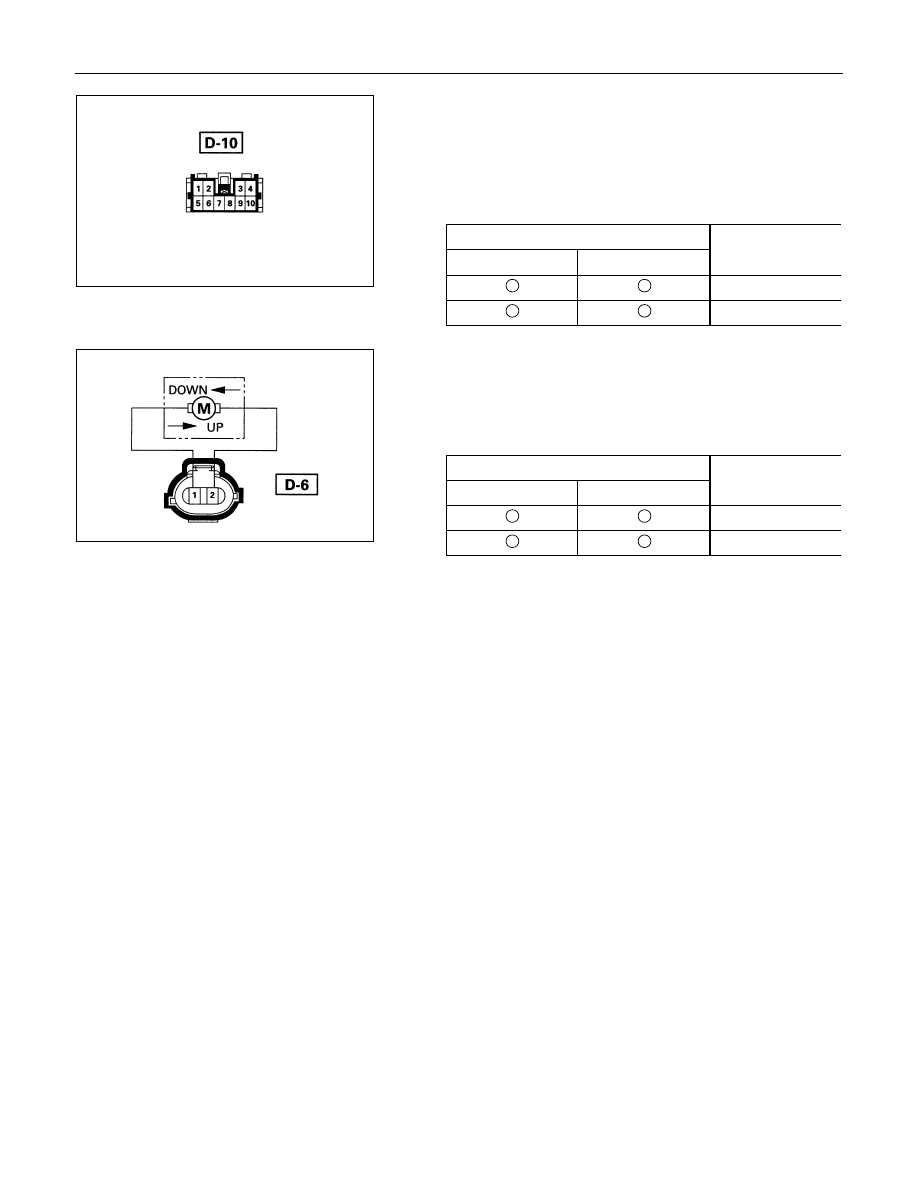
Driver Seat Side Power Window Motor
1. Driver Seat Side Power Window & Door Lock Switch
Connector Circuit
Disconnect the switch connector, apply the battery voltage
(12V) to the harness side connector terminals and check
operation.
Connecting terminals
Operation
1 (L/R)
10 (L/W)
direction
-
+
DOWN
+
-
UP
2. Driver Seat Side Power Window Motor Connector
Circuit
Disconnect the switch connector, apply the battery voltage
(12V) to the motor side connector terminals and check
operation.
Connecting terminals
Operation
1
2
direction
+
-
DOWN
-
+
UP
8-306 ELECTRICAL-BODY AND CHASSIS
Harness side
Front Passenger’s Power Window Motor
1. Front Passenger’s Power Window Switch & Door Lock
Switch Connector Circuit
Disconnect the motor connector, apply the battery voltage
(12V) to the harness side connector terminals and check
operation.
Connecting terminals
Operation
6 (L/R)
10 (L/W)
direction
-
+
DOWN
+
-
UP
2. Front Passenger’s Power Window Motor Connector
Circuit
Disconnect the switch connector, apply the battery voltage
(12V) to the motor side connector terminals and check
operation.
Connecting terminals
Operation
1
2
direction
+
-
DOWN
-
+
UP
Нет комментариевНе стесняйтесь поделиться с нами вашим ценным мнением.
Текст