Isuzu D-Max / Isuzu Rodeo (TFR/TFS). Manual — part 1763

DIAGNOSIS 7A2-103
Step
Action
Yes
No
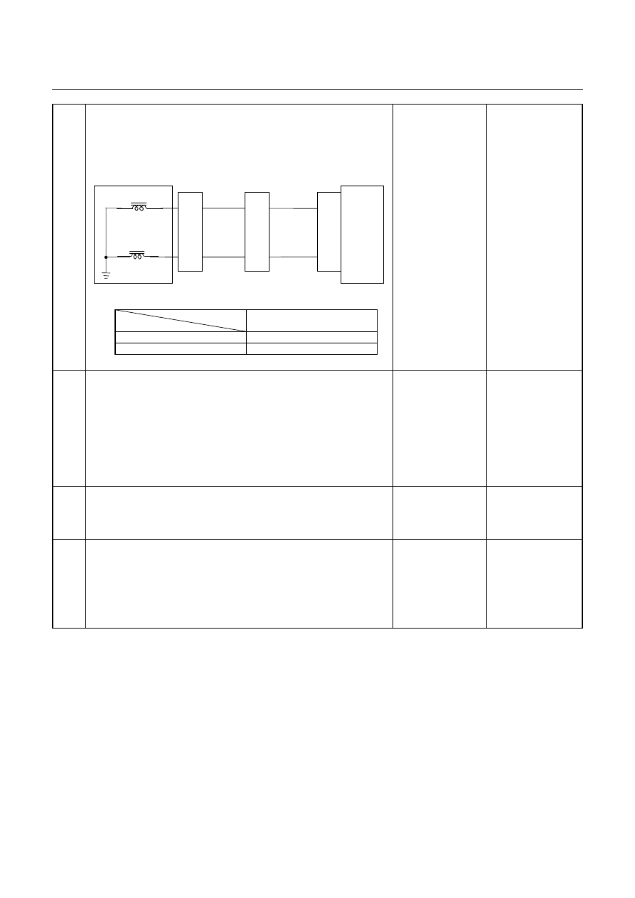
6
Inspect the output voltage and throttle opening signal of the
throttle position sensor using a Tech 2 or circuit tester.
Is a voltage value in proportion to the throttle opening output?
TPS
TCM
A16
C56
(28)
C94
(16)
RED/WHT
C56
(49)
(38)
(57)
(69)
ECM
A47 (GND)
A35 (Output)
A26
A55 (+5V)
A69 (Idle SW)
Go to Step 7
Repair the defect or
replace.
7
Check of power supply to and earth of TCM.
Are the power supply and earth proper?
TCM
A1 (+B)
B5
B15
H23
(15)
C95
(5)
(15)
BLK/YEL
BLK
BLK
Battery
C94
(1)
BLK
Go to Step 8
Check the power
source harness and
earth harness (bolt
tightening to the
body).
8
Is the stall revolution correct in D, 3, 2 and L range? Refer the
STALL TEST section in this manual.
Go to Step 9
Repair the defect or
replace.
9
Is the line pressure correct? Refer the LINE PRESSURE TEST
section in this manual.
Trouble in the AT
assembly or control
valve.
Repair the defect or
replace.
7A2-104 DIAGNOSIS
No. B4: Large Shock When Shift Lever is Changed to N to D
Range or N to R Range
Description:
•
Large shock is felt when selecting D or R range from N range during the idling after warming up.
Diagnosis Hints:
•
Check the entire condition of the vehicle for unusual other than AT including faulty engine mount, exhaust
hanger, etc.
•
When the fail-safe operation, select shock may grow worse. In such a case, check for the DTC. If no DTC is
issued, shock due to faulty operation of the control valve or burnt clutch is considered.
Possible Cause:
•
High
engine
idling.
•
Dislocated select lever, improper inhibitor switch adjusting point.
•
Faulty or insufficient tightening of engine mount, exhaust mount.
•
Play of suspension.
•
Burnt
clutch.
•
Too low or high line pressure.
•
Faulty input signal system.
•
Faulty control valve. (faulty operation or sticking of accumulator)

DIAGNOSIS 7A2-105
No. B5: Engine Stalls When Selecting From N Range to
R, D, 3, 2 or L Range
Description:
•
The engine stalls when selecting from N or P range to a run range during the engine idling.
Diagnosis Hints:
•
As causes attributable to the engine, faulty idle up, insufficient engine output, etc. are considered.
•
As a cause of the AT system, faulty lockup piston system (lockup engine stall) is considered.
•
If the oil through resistance increases remarkably due to clogged oil cooler or some other reason, or if the ATF
level decreases, the lock-up piston works causing the engine stall.
Possible Cause:
•
Disordered idling speed, faulty idle up, faulty engine output, shortage output.
•
Insufficient ATF quantity (dropped level).
•
Clogged oil cooler (foreign substance mixed in).
•
Faulty lock-up piston (clogged oil passage of solenoid drive circuit, faulty operation).
Step
Action
Yes
No
1
Gear ratio trouble diagnosis.
Travel in the following sequence for about 7 seconds or more in
each range: Start in the L range (1st) to 2 range (2nd) to 3 range
(3rd) to D range (4th) (to detect the gear ratio trouble exactly, this
process should be carried out)
Go to Step 2
Go to Step 2
2
Are any DTCs stored?
Go to DTC Chart
Go to Step 3
3
Are the quantity, contamination and smell normal?
If the ATF level is
low, replenish up to
the specified level.
Go to Step 4
If ATF is extremely
black and
contaminated and
smells burnt, slip of
the clutch is
supposed.
Overhaul the AT
unit.
4
Check of engine idle up speed
Does the idle speed increase when the air conditioning or other
electric load is turned on?
Go to Step 5
Repair the defect or
replace.
7A2-106 DIAGNOSIS
Step
Action
Yes
No
5
Inspection of electrical or mechanical fault
When the D range is selected from D at idling speed, is the signal
to the lock-up solenoid turned off using the Tech 2 or circuit
tester?
Control Valve
TCM
B17
B23
BLK
Lock-up Solenoid
Terminal
Assembly
VIO
Line Pressure Solenoid
E54
(4)
(6)
H23
(14)
(6)
C95
(17)
(23)
BLK
VIO
TCM terminal
Lock-up
B17
At lock-up
Approx. 7.2 V (AC range)
At unlock-up
Approx. 4.0V (AC range)
Go to Step 6
Find a cause to turn
on the lockup
solenoid
6
Check of clogging of oil cooler
When blowing the oil cooler outlet with air, does some foreign
substance come out?
Clean or replace the
oil cooler.
Go to Step 7
Clogged lock-up
solenoid oil
passage. Faulty
operation of lock-up
piston.
Faulty control valve.
7
Is the stall revolution correct in D, 3, 2 and L range? Refer the
STALL TEST section in this manual.
Go to Step 8
Repair the defect or
replace.
8
Is the line pressure correct? Refer the LINE PRESSURE TEST
section in this manual.
Trouble in the AT
assembly or control
valve.
Repair the defect or
replace.
Нет комментариевНе стесняйтесь поделиться с нами вашим ценным мнением.
Текст