Isuzu D-Max / Isuzu Rodeo (TFR/TFS). Manual — part 1329
8–236 ELECTRICAL-BODY AND CHASSIS
Installation
To Install, follow the removal steps in the reverse order.
FUEL TANK UNIT
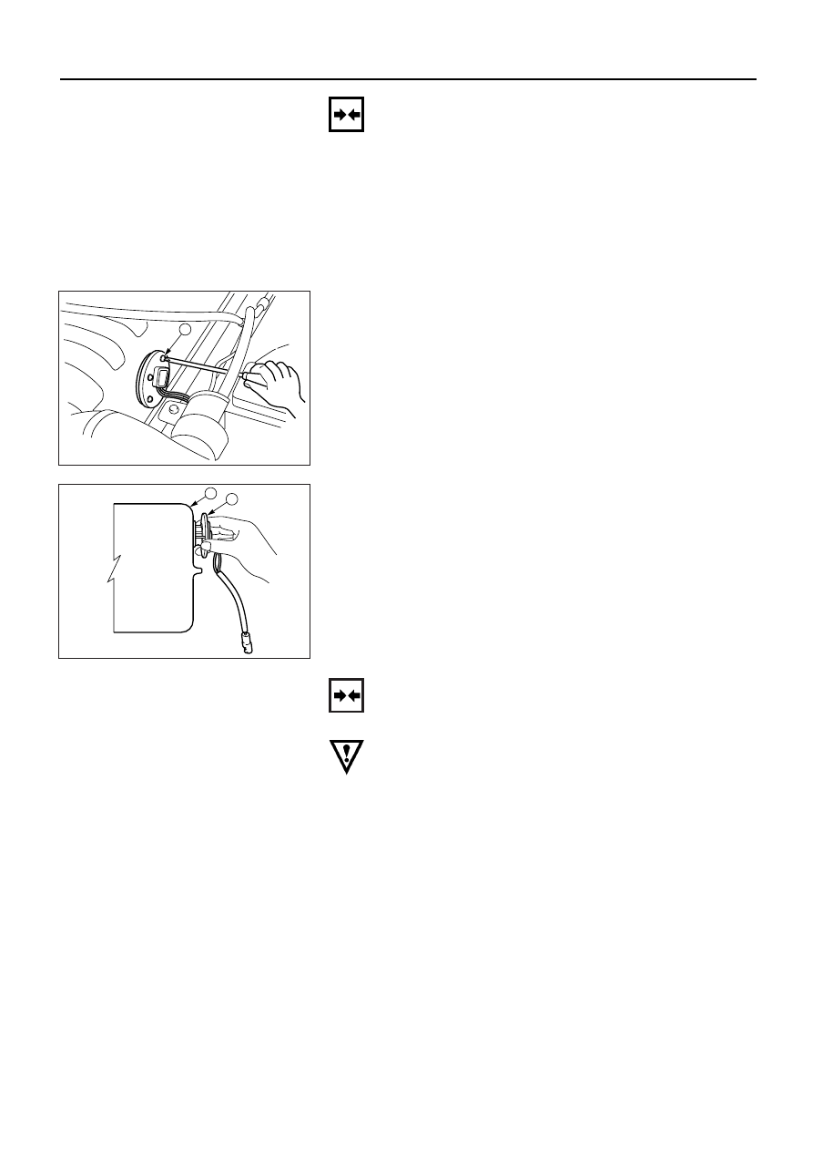
Removal
1. Disconnect the fuel tank unit connector.
2. Loosen the screws
1.
1
140RV008
3. Remove the fuel tank unit 2 from the fuel tank 3.
3
2
140RV009
Installation
Follow the removal procedure in the reverse order to
install the fuel tank unit.
Pay close attention to the important points mentioned in
the following paragraphs.
Rubber Seal
Be absolutely sure that the fuel tank unit rubber seal is
correctly seated.
Connector
Be absolutely sure that the fuel tank unit connector is
securely connected.
This will prevent a poor contact and an open circuit.

ELECTRICAL-BODY AND CHASSIS 8–237
VEHICLE SPEED SENSOR (INSTALLED ON THE
TRANSMISSION)
Removal
1. Disconnect the connector.
2. Remove the vehicle speed sensor body by rotating it.
Speed sensor
This illustration is based on MUA T/M
826RV043
Installation
To Install, follow the removal steps in the reverse order,
noting the following point.
Tighten the vehicle speed sensor to the specified torque.
Vehicle Speed Sensor Tightening Torque kg·m (lb·ft/N·m)
2.5 ± 0.5 (18 ± 3.6 / 25 ± 4.9)
8–238 ELECTRICAL-BODY AND CHASSIS
INSPECTION AND REPAIR
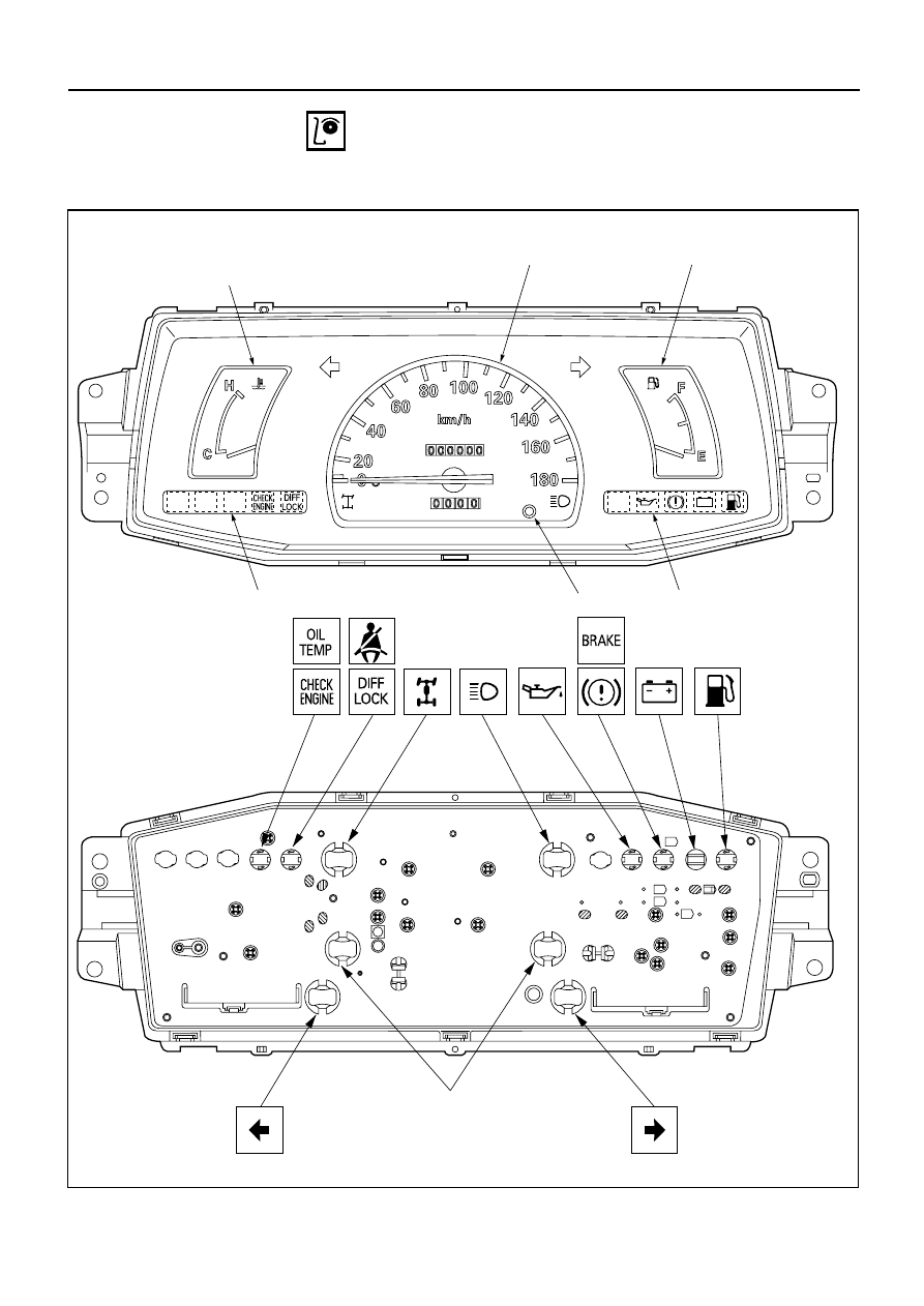
Warning, indicator and illumination light position
W/O Tachometer (Gasoline engine)
Illumination light
Reset knob
Engine coolant
temperature gauge
Fuel gauge
Speedometer
Warning light lens
Warning light lens
+
-
826RV035
(This illustration is based on the Km/h meter)

ELECTRICAL-BODY AND CHASSIS 8–239
W/O Tachometer (Diesel engine)
Illumination light
Reset knob
Engine coolant
temperature gauge
Fuel gauge
Speedometer
Warning light lens
Warning light lens
+
-
826RV036
(This illustration is based on the Km/h meter)
Нет комментариевНе стесняйтесь поделиться с нами вашим ценным мнением.
Текст