Isuzu D-Max / Isuzu Rodeo (TFR/TFS). Manual — part 627

7A1–8 AUTOMATIC TRANSMISSION (4L30-E)
CONTROL SYSTEM DIAGRAM
AUTOMATIC TRANSMISSION ASSEMBLY
ENGINE
LOCKUP PISTON
TORQUE
CONVERTER
INPUT SHAFT
PLANETARY GEAR
MULTIPLATE CLUTCH
MULTIPLATE BRAKE
BRAKE BAND
ONE WAY CLUTCH
OUTPUT SHAFT
TIRE
FINAL DRIVE GEAR
DRIVE SHAFT
OIL PUMP
SERVO MECHANISM
CONTROL VALVE
:
POWER
TRANSMIT
:
OIL PRESSURE
CONTROL
:
MECHANICAL
SIGNAL
:
ELECTRONIC
SIGNAL
OIL TEMP.
SENSOR
TORQUE CONVERTER
CLUTCH SOLENOID
SHIFT SOLENOID A
SHIFT SOLENOID B
BAND APPLY
SOLENOID
FORCE MOTOR
MANUAL VALVE
VEHICLE SPEED
SENSOR
MODE
SWITCH
CHECK TRANS LAMP
POWER LAMP
KICKDOWN SWITCH
BRAKE SWITCH
POWER MODE SWITCH
AIR CONDITIONING
SWITCH
TRANSMISSION CONTROL
MODULE (TCM)
• SHIFT CONTROL
• BAND APPLY CONTROL
• TORQUE CONVERTER CLUTCH
CONTROL
• LINE PRESSURE CONTROL
• SAFETY MODE
• ON-BOARD DIAGNOSTIC
SYSTEM
• TORQUE MANAGEMENT
SHIFT INDICATOR LAMP
A/T SHIFT INDICATOR
CONTROL UNIT
(
(
CRANK ANGLE SENSOR
THROTTLE POSITION
SENSOR
ENGINE COOLANT
TEMPERATURE SENSOR
ECM
C07LW001
AUTOMATIC TRANSMISSION (4L30-E) 7A1–9
1.
SHIFT CONTROL
The transmission gear is shifted according to the
shift pattern selected by the driver.
In shifting gears, the gear ratio is controlled by the
ON/OFF signal using the shift solenoid A and the
shift solenoid B.
2.
BAND APPLY CONTROL
The band apply is controlled when in the 3-2
downshift (engine overrun prevention) and the
garage shift (shock control).
The band apply solenoid is controlled by the signal
from the Pulse Width Modulation (PWM) to regulate
the flow of the oil.
3.
TORQUE CONVERTER CLUTCH CONTROL
The clutch ON/OFF is controlled by moving the
converter clutch valve through shifting Torque
Converter Clutch (TCC) solenoid using the ON/OFF
signal.
4.
LINE PRESSURE CONTROL
The throttle signal allows the current signal to be
sent to the force motor. After receiving the current
signal, the force motor activates the pressure
regulator valve to regulate the line pressure.
5.
ON-BOARD DIAGNOSTIC SYSTEM
Several malfunction displays can be stored in the
Transmission Control Module (TCM) memory, and
read out of it afterward.
The serial data lines, which are required for the
testing of the final assembly and the coupling to
other electronic modules, can be regulated by this
function.
6.
FAIL-SAFE MECHANISM
If there is a problem in the transmission system, the
TCM will go into a “backup” mode. The vehicle can
still be driven, but the drive must use the gear lever
to shift gears.
7.
TORQUE MANAGEMENT CONTROL
The TCM sends the absolute spark advance signal
to the Engine Control Module (ECM) while the
transmission is being shifted, to control the engine
spark timing in compliance with the vehicle running
condition to reduce the shocks caused by the
change of speed.

7A1–10 AUTOMATIC TRANSMISSION (4L30-E)
SHIFT MODE CONTROL
1
Mode type
Mode type
Select lever position
Normal drive mode (NOR)
Entire range (excluding “R”)
Power drive mode (PWR)
Entire range (excluding “R”)
2
Mode selection
SWITCH (SW)
LAMP
Mode type
PWR/NOR. SW
POWER DRIVE LAMP
Normal drive mode (NOR)
OFF
OFF
Power drive mode (PWR)
ON
ON
3
Comparison of mode
(1)
The normal drive mode is set at the normal shift points.
(2)
The shift points of the power drive mode are shifted to the higher speed side, compared to the
normal drive mode.
Shift diagram
2
3
3
4
1
2
2
1
2
3
4
3
N: Normal drive mode
P: Power drive mode
Amount of
throttle
opening
Speed
mph(km/h)
N P
P
P
N
N
AUTOMATIC TRANSMISSION (4L30-E) 7A1–11
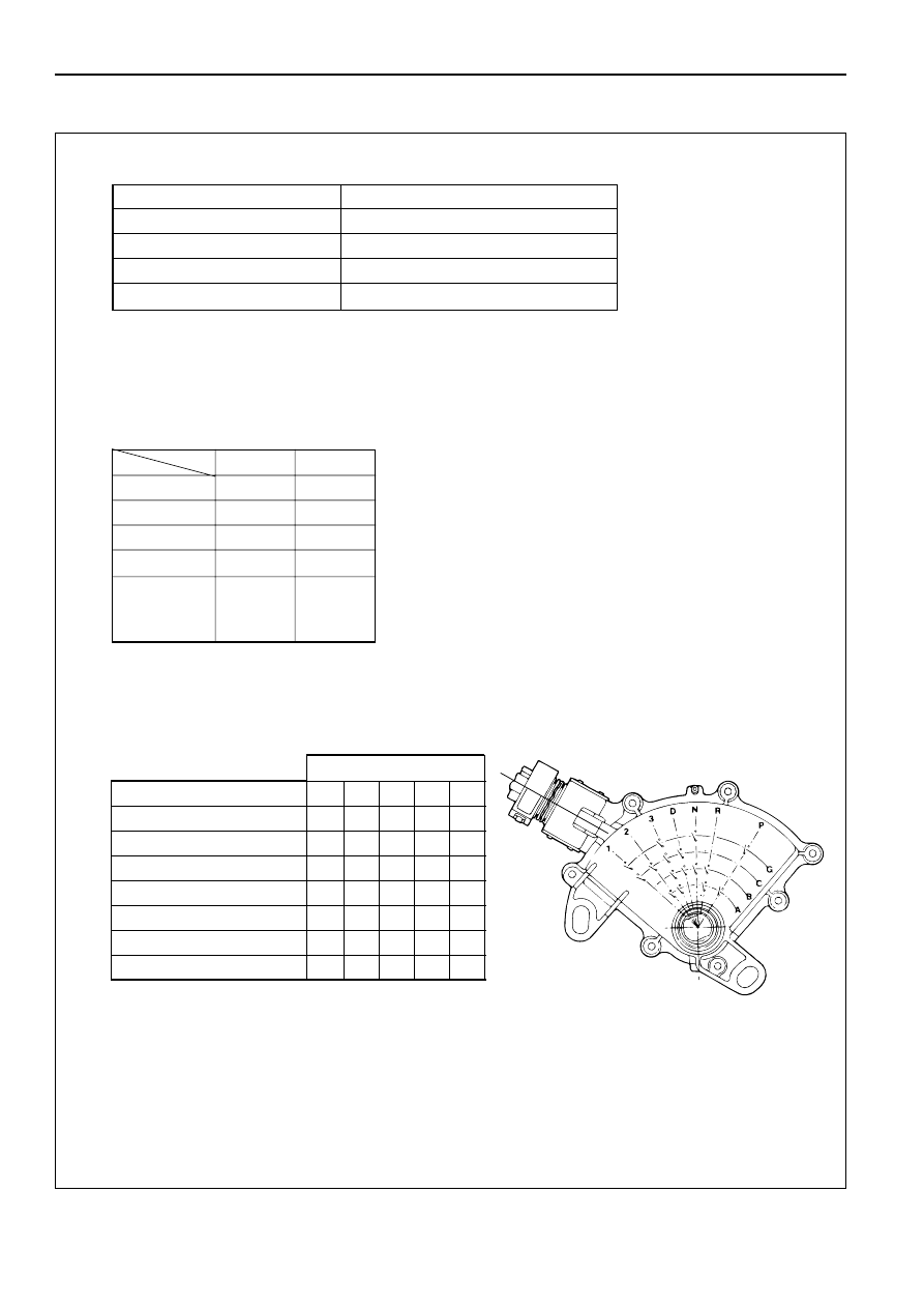
GEAR SHIFT CONTROL
1
Shift pattern
2
Gear position
The gear is selected by ON/OFF of two solenoids.
3
Selecting gear position
Seven types of positions can be selected according to 5 signals from the mode switch as shown
below.
SELECT LEVER RANGE
SHIFT PATTERN
D (Drive)
1
2TCC
3TCC
4TCC
3 (Third)
1
2TCC
3TCC
4TCC
2 (Second)
1
2TCC
3TCC
L (First)
1
2
→
←
→
←
←
←
←
→
←
→
←
→
←
→
←
TCC = Torque Converter Clutch
GEAR
SOL
A
B
4 (Fourth)
✕
✕
3 (Third)
●
●
✕
2 (Second)
●
●
●
●
1 (First)
✕
●
●
P (Park)
R (Reverse)
✕
●
●
N (Neutral)
●
●
= ON
✕ = OFF
SOLENOID A
ON
→
PRESSURE TO
(Normally closed)
SHIFT VALVE
SOLENOID B
OFF
→
PRESSURE TO
(Normally open)
SHIFT VALVE
MODE SW TERMINALS
SELECT LEVER RANGE
5(D) 8(A) 7(B) 6(C) 3(G)
P (Park)
•
•
•
R (Reverse)
•
•
•
N (Neutral)
•
•
•
D (Drive)
•
•
•
3 (Third)
•
•
•
•
•
2 (Second)
•
•
•
L (First)
•
•
•
•
= Continuity
Нет комментариевНе стесняйтесь поделиться с нами вашим ценным мнением.
Текст