Isuzu D-Max / Isuzu Rodeo (TFR/TFS). Manual — part 2031
3B-14 STEERING
1. Installation of Tester
•
Power Steering Tester : 5-8840-0135-0
(J-29877-A)
Adapter; Power Steering Tester :
5-8840-0136-0
(J-33996)
1
Oil Pressure Gauge with Shut off Valve
2
Shut off Valve
3
Adapter (to steering unit)
4
Adapter (to oil pump)
•
Installation Procedure;
Disconnect the hose on the outlet side of the pump.
Connect the gauge hose closest to the power steering
gauge shut off valve to the hose on the vehicle. Connect
the gauge hose furthest from the shut off valve to the
outlet side of the power steering pump.
2. Bleeding
•
Open stop valve fully.
•
Refer to air bleeding procedure.
3. Measurement of Fluid Pressure
•
Open stop valve fully.
•
Increase engine speed to 1500 rpm.
•
Measure the fluid pressure when the steering wheel is
turned to lock in both directions.
Fluid Pressure
kg/cm
2
(psi/kPa)
95 - 100
(1351 - 1422/9316 - 9806) (C22, C20 Series Engine Model)
100 - 105
(1422 - 1493/9806 - 10297) (4J Series Engine Model)
Diagnosis:
(1) When pressure is higher than Specified pressure, the valve
within the oil pump is defective.
(2) When the pressure is lower than Specified pressure.
•
Return steering wheel to straight-ahead position.
•
Close stop valve completely.
•
Hold engine running at 1500 rpm, and take reading of
the pressure gauge.
Fluid Pressure
kg/cm
2
(psi/kPa)
Possible trouble
95 - 100
(1351 -1422/9316 - 9806)
(C22, C20 Series Engine Model)
100 - 105
(1422 - 1493/9806 - 10297)
(4J Series Engine Model)
Lower than 95 (1351/9316)
(C22, C20 Series Engine Model)
Lower than 100 (1422/9806)
(4J Series Engine Model)
Oil pump
Steering unit
STEERING 3B-15
STEERING MECHANISM
GENERAL DESCRIPTION
STEERING MECHANISM
3B-16 STEERING
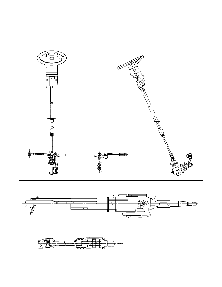
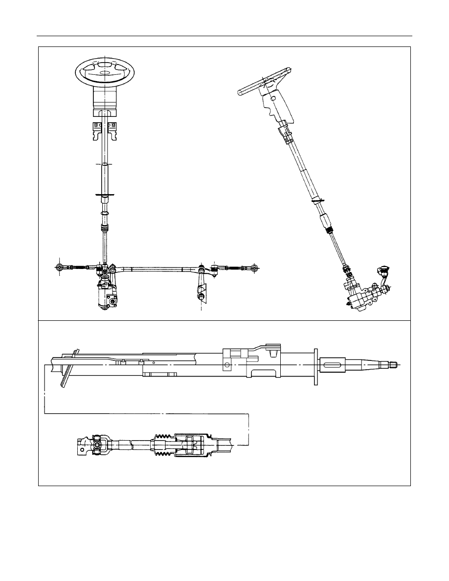
The steering mechanism comprises a steering wheel, steering column, steering shaft, steering unit, and steering
linkage.
The steering shaft is equipped with slid joints to prevent vehicle vibration from transferring to the steering wheel.
STEERING 3B-17
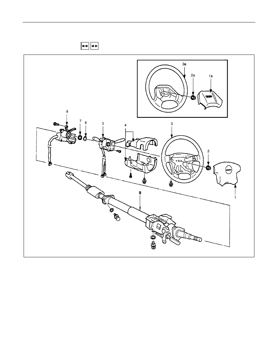
STEERING COLUMN
REMOVAL AND INSTALLATION
Removal Steps
V
1., 1a. Horn shroud
2., 2a. Nut
V
3., 3a.Steering wheel
4. Steering cowl
5. Combination switch
6. Snap ring
7. Bushing
V
8. Steering lock and bearing
V
9. Steering column assembly
Installation Steps
V
9. Steering column assembly
V
8. Steering lock and bearing
7. Bushing
6. Snap ring
5. Combination switch
4. Steering cowl
V
3., 3a. Steering wheel
V
2., 2a. Nut
V
1., 1a. Horn shroud
Нет комментариевНе стесняйтесь поделиться с нами вашим ценным мнением.
Текст