Isuzu D-Max / Isuzu Rodeo (TFR/TFS). Manual — part 1886

DIAGNOSIS 7A2-160
No.
Wire
Color
Pin Name
Input /
Output
Connected to
Measurement
Item
Measurement
Condition
Standard
Inspection
Point at
Trouble
At key switch
ON
Battery
voltage
Related
harness
B24
WHT V ign (Ignition Power Supply)
Input
Key switch
Voltage
At Key switch
OFF
Less than 2V Fuse
7.14ms 7.14ms
Time Time
0.714ms 6.426ms
V
olt
age
Off duty 10% =Throttle Position 0%
V
olt
age
Off duty 90% =Throttle Position 100%
Engine Speed Sensor Reference Wave Form
Measurement Terminal: A7 (+)
B5 (-)
Measurement Scale: 5V/div
20ms/div
Measurement Condition: At engine speed 1500rpm
Vehicle Speed Sensor Out Reference Wave Form
Measurement Terminal: A10 (+) B5 (-)
Measurement Scale: 5V/div
50ms/div
Measurement Condition: Vehicle speed 20km/h at L
range in 1st gear
Turbine Sensor Reference Wave Form
Measurement Terminal: B3 (+)
B5 (-)
Measurement Scale: 5V/div
500ms/div
Measurement Condition: Vehicle speed 20km/h at L
range in 1st gear
Vehicle Speed Sensor Reference Wave Form
Measurement Terminal: B13 (+) B5 (-)
Measurement Scale: 5V/div
2ms/div
Measurement Condition: Vehicle speed 20km/h at L
range in 1st gear
DIAGNOSIS 7A2-161
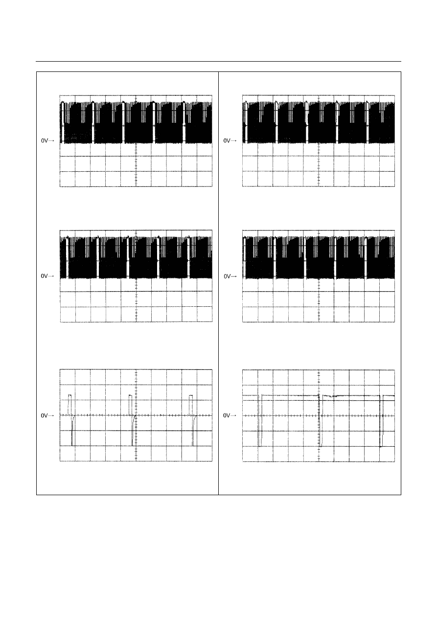
Low & Reverse Brake Duty Solenoid Reference
Wave Form
Measurement Terminal: B6 (+)
B22 (-)
Measurement Scale: 5V/div
10ms/div
Measurement Condition: P, N range in idle
2-4 Brake Duty Solenoid Reference Wave Form
Measurement Terminal: B7 (+)
B22 (-)
Measurement Scale: 5V/div
20ms/div
Measurement Condition: P, N range in idle
High Clutch Duty Solenoid Reference Wave Form
Measurement Terminal: B8 (+)
B22 (-)
Measurement Scale: 5V/div
20ms/div
Measurement Condition: P, N range in idle
Low Clutch Duty Solenoid Reference Wave Form
Measurement Terminal: B9 (+)
B22 (-)
Measurement Scale: 5V/div
20ms/div
Measurement Condition: D range 4th gear
Lock-up Duty Solenoid Reference Wave Form
Measurement Terminal: B17 (+) B5 (-)
Measurement Scale: 10V/div
5ms/div
Measurement Condition: Unlock-up condition
Lock-up Duty Solenoid Reference Wave Form
Measurement Terminal: B17 (+) B5 (-)
Measurement Scale: 10V/div
5ms/div
Measurement Condition: Lock-up condition

MEMO
ON-VEHICLE SERVICE (JR405E) 7A3-1
SECTION 7A3
ON-VEHICLE SERVICE (JR405E)
TABLE OF CONTENTS
PAGE
Description . . . . . . . . . . . . . . . . . . . . . . . . . . . . . .. 7A3 –
2
Automatic Transmission Fluid (ATF) . . . . . . . . . . . . . . . . . . . . 7A3 –
2
ATF Level . . . . . . . . . . . . . . . . . . . . . . . . . . . . . . . 7A3 –
2
ATF Change . . . . . . . . . . . . . . . . . . . . . . . . . . . . . . 7A3 –
3
Transmission Control Module (TCM) . . . . . . . . . . . . . . . . . . . 7A3 –
4
Throttle Position Sensor . . . . . . . . . . . . . . . . . . . . . . . . 7A3 –
5
Inhibitor Switch . . . . . . . . . . . . . . . . . . . . . . . . . . . ... 7A3 –
6
Speed Sensor . . . . . . . . . . . . . . . . . . . . . . . . . . . . .. 7A3 –
8
Turbine Sensor . . . . . . . . . . . . . . . . . . . . . . . . . . . . 7A3 –
8
Power and 3rd Start Switch . . . . . . . . . . . . . . . . . . . . . . ... 7A3 –
9
Select Lever . . . . . . . . . . . . . . . . . . . . . . . . . . . . . . 7A3 –10
Shift Cable . . . . . . . . . . . . . . . . . . . . . . . . . . . . . ... 7A3 –13
Solenoids, Oil Pressure Switch and Oil Temperature Sensor . . . . . . . . . 7A3 –16
Control Valve Assembly . . . . . . . . . . . . . . . . . . . . . . . . . 7A3 –18
Flushing the Transmission Fluid Cooler and Line . . . . . . . . . . . . . ... 7A3 –19
Transmission Assembly . . . . . . . . . . . . . . . . . . . . . . . . . 7A3 –20
Нет комментариевНе стесняйтесь поделиться с нами вашим ценным мнением.
Текст