Isuzu D-Max / Isuzu Rodeo (TFR/TFS). Manual — part 826

6E–33
3.2L ENGINE DRIVEABILITY AND EMISSIONS
10.This vehicle is equipped with a ECM which utilizes
an electrically erasable programmable read only
memory (EEPROM).
On- Board Diagnostic (OBD) System Check
Step
Action
Value(s)
Yes
No
1
1. Ignition “ON,” engine “OFF.”
2. Observe the malfunction indicator lamp (MIL or
“Check Engine” lamp).
Is the MIL (“Check Engine” lamp)“ON?”
—
Go to
Step 2
Go to
No MIL
(“Check
Engine” lamp)
2
1. Ignition “OFF.”
2. Install a Tech 2.
3. Ignition “ON.”
4. Attempt to display ECM engine data with the Tech 2.
Does the Tech 2 display ECM data?
—
Go to
Step 3
Go to
Step 8
3
1. Using the Tech 2 output tests function, select MIL
(“Check Engine” lamp) dash lamp control and
command the MIL (“Check Engine” lamp) “OFF.”
2. Observe the MIL (“Check Engine” lamp).
Did the MIL (“Check Engine” lamp) turn “OFF?”
—
Go to
Step 4
Go to
MIL
(“Check
Engine” lamp)
On Steady
4
Attempt to start the engine.
Did the engine start and continue to run?
—
Go to
Step 5
Go to
Cranks
But Will Not
Run
5
Select “Display DTCs” with the Tech 2.
Are any DTCs stored?
—
Go to
Step 6
Go to
Step 7
6
Are two or more of the following DTCs stored? P0107,
P0108, P0113, P0118, P0122, P0123.
—
Go to
“Multiple
ECM
Information
Sensor DTCs
Set”
Go to
applicable
DTC table
7
Compare ECM data values displayed on the Tech 2 to
the typical engine scan data values.
Are the displayed values normal or close to the typical
values?
—
Refer to
Typical scan
data value
Refer to
indicated
Component
System
Checks
8
1. Ignition “OFF,” disconnect the ECM.
2. Ignition “ON,” engine “OFF.”
3. Check the Class 2 data circuit for an open, short to
ground, or short to voltage. Also, check the DLC
ignition feed circuit for an open or short to ground
and the DLC ground circuit for an open.
4. If a problem is found, repair as necessary.
Was a problem found?
—
Go to
Step 2
Go to
Step 9
9
1. Attempt to reprogram the ECM. Refer to
On-Vehicle Service in Engine Control Module and
Sensors for procedures.
2. Attempt to display ECM data with the Tech 2.
Does the Tech 2 display ECM engine data?
—
Go to
Step 2
Go to
Step 10
10
Replace the ECM.
Is the action complete?
—
Go to
Step 2
—
6E–34
3.2L ENGINE DRIVEABILITY AND EMISSIONS
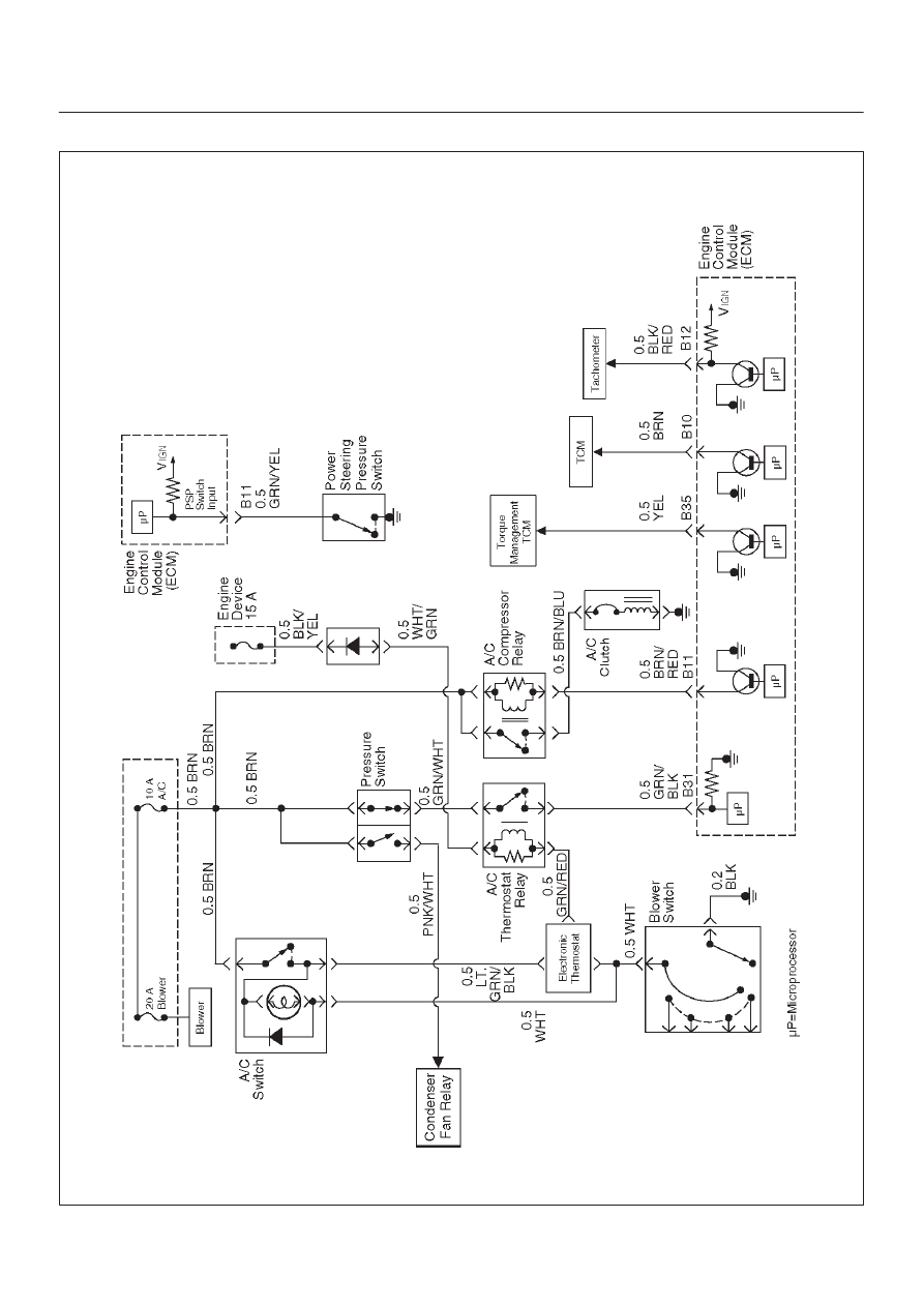
A/C Clutch Control Circuit Diagnosis
060RW041

6E–35
3.2L ENGINE DRIVEABILITY AND EMISSIONS
Circuit Description
When air conditioning and blower fan are selected, and if
the system has a sufficient refrigerant charge, a 12-volt
signal is supplied to the A/C request input of the Engine
Control Module ECM. The A/C request signal may be
temporarily canceled during system operation by the
electronic thermostat in the evaporator case. The
electronic thermostat may intermittently remove the
control circuit ground for the A/C thermostat relay to
prevent the evaporator from forming ice. When the A/C
request signal is received by the ECM, the ECM supplies
a ground from the compressor clutch relay if the engine
operating conditions are within acceptable ranges. With
the A/C compressor relay energized, voltage is supplied
to the compressor clutch coil.
The ECM will enable the compressor clutch to engage
whenever A/C has been selected with the engine running,
unless any of the following conditions are present:
D
The throttle is greater than 90%.
D
The ignition voltage is below 10.5 volts.
D
The engine speed is greater than 4500 RPM for 5
seconds or 5400 RPM.
D
The engine coolant temperature (ECT) is greater than
125
°
C (257
°
F).
D
The intake air temperature (IAT) is less than 5
°
C
(41
°
F).
D
The power steering pressure switch signals a cramped
position.
Diagnostic Aids
To diagnose an the intermittent fault, check for the
following conditions:
D
Poor connection at the ECM–Inspect connections for
backed-out terminals, improper mating, broken locks,
improperly formed or damaged terminals, and poor
terminal-to-wire connection.
D
Damaged harness–Inspect the wiring harness for
damage. If the harness appears to OK, observe the
A/C clutch while moving connectors and wiring
harnesses related to the A/C. A sudden clutch
malfunction will indicate the source of the intermittent
fault.
A/C Clutch Diagnosis
This chart should be used for diagnosing the electrical
portion of the A/C compressor clutch circuit. A Tech 2 will
be used in diagnosing the system. The Tech 2 has the
ability to read the A/C request input to the ECM. The Tech
2 can display when the ECM has commanded the A/C
clutch “ON.” The Tech 2 should have the ability to
override the A/C request signal and energize the A/C
compressor relay.
Test Description
IMPORTANT:
Do not engage the A/C compressor
clutch with the engine running if an A/C mode is not
selected at the A/C control switch.
The numbers below refer to the step numbers on the
Diagnostic Chart:
3. This a test determine is the problem is with the
refrigerant system. If the switch is open, A/C
pressure gauges will be used to determine if the
pressure switch is faulty or if the system is partially
discharged or empty.
4. Although the normal complaint will be the A/C clutch
failing to engage, it is possible for a short circuit to
cause the clutch to run when A/C has not been
selected. This step is a test for that condition.
7. There is an extremely low probability that both relays
will fail at the same time, so the substitution process
is one way to check the A/C Thermostat relay. Use
a known good relay to do a substitution check.
9. The blower system furnishes a ground for the A/C
control circuit, and it also shares a power source
through the Heater and A/C Relay. The blower
must be “ON” in order to test the A/C system.
A/C Clutch Control Circuit Diagnosis
Step
Action
Value(s)
Yes
No
1
Was the “On-Board Diagnostic (OBD) System Check”
performed?
—
Go to
Step 2
Go to
OBD
System
Check
2
Are any other DTCs stored?
—
Go to the
other DTC
chart(s) first
Go to
Step 3
3
1. Disconnect the electrical connector at the pressure
switch located on the receiver/drier.
2. Use an ohmmeter to check continuity across the
pressure switch (BRN to GRN/WHT).
Is the pressure switch open?
—
Go to Air
Conditioning
to diagnose
the cause of
the open
pressure
switch
Go to
Step 4

6E–36
3.2L ENGINE DRIVEABILITY AND EMISSIONS
A/C Clutch Control Circuit Diagnosis
(Cont'd)
Step
No
Yes
Value(s)
Action
4
IMPORTANT: Before continuing with the diagnosis, the
following conditions must be met:
D
The intake air temperature must be greater than
15
°
C. (60
°
F).
D
The engine coolant temperature must be less
than 119
°
C (246
°
F).
1. A/C “OFF.”
2. Start the engine and idle for 1 minute.
3. Observe the A/C compressor.
Is the A/C compressor clutch engaged even though
A/C has not been requested?
—
Go to
Step 45
Go to
Step 5
5
1. Idle the engine.
2. A/C “ON”.
3. Blower “ON”.
4. Observe the A/C compressor.
Is the A/C compressor magnetic clutch engaged?
—
Refer to
Diagnostic
Aids
Go to
Step 6
6
1. Engine idling.
2. A/C “ON”.
3. Blower “ON”.
4. Observe the “A/C Request” display on the Tech 2.
Does the “A/C Request” display indicate “Yes?”
—
Go to
Step 34
Go to
Step 7
7
Temporarily substitute the A/C compressor relay in
place of the A/C thermostat relay, then repeat Step 5.
Did the “A/C Request” display indicate “Yes?”
—
Go to
Step 8
Go to
Step 9
8
Replace the original A/C thermostat relay.
Is the action complete?
—
Verify repair
—
9
Dose the blower operate?
—
Go to
Step 10
Go to
Step 11
10
Repair the blower.
Is the action complete?
—
Verify repair
—
11
Check for a faulty 10a A/C fuse in the passenger
compartment fuse panel.
Was the 10A fuse OK?
—
Go to
Step 13
Go to
Step 12
12
Check for short circuit and make repairs if necessary.
Replace the 10A A/C fuse.
Is the action complete?
—
Verify repair
—
13
1. Ignition “ON.”
2. Use a DVM to check voltage at the positive A/C
switch wire (BRN).
Was voltage equal to the specified value?
B+
Go to
Step 15
Go to
Step 14
14
Repair the open wire (BRN) between the A/C switch
and the A/C fuse.
Is the action complete?
—
Verify repair
—
Нет комментариевНе стесняйтесь поделиться с нами вашим ценным мнением.
Текст