Isuzu Rodeo UE. Manual — part 327
6E2–63
RODEO 6VD1 3.2L ENGINE DRIVEABILITY AND EMISSIONS
Electronic Ignition System Diagnosis
If the engine cranks but will not run or immediately stalls,
the Engine Cranks But Will Not Start chart must be used
to determine if the failure is the ignition system or the fuel
system. If DTC P0300 through P306, P0341, or P0336 is
set, the appropriate diagnostic trouble code chart must be
used for diagnosis.
If a misfire is being experienced with no DTC set, refer to
the
Symptoms section for diagnosis.
EVAP Canister Purge Solenoid
A continuous purge condition with no purge commanded
by the PCM will set a DTC P1441. Refer to the DTC
charts for further information.
Visual Check of The Evaporative
Emission Canister
f
If the canister is cracked or damaged, replace the
canister.
f
If fuel is leaking from the canister, replace the canister
and check hoses and hose routing.
Fuel Metering System Check
Some failures of the fuel metering system will result in an
“Engine Cranks But Will Not Run” symptom. If this
condition exists, refer to the
Engine Cranks But Will Not
Run chart. This chart will determine if the problem is
caused by the ignition system, the PCM, or the fuel pump
electrical circuit.
Refer to
Fuel System Electrical Test for the fuel system
wiring schematic.
If there is a fuel delivery problem, refer to
Fuel System
Diagnosis, which diagnoses the fuel injectors, the fuel
pressure regulator, and the fuel pump. If a malfunction
occurs in the fuel metering system, it usually results in
either a rich HO2S signal or a lean HO2S signal. This
condition is indicated by the HO2S voltage, which causes
the PCM to change the fuel calculation (fuel injector pulse
width) based on the HO2S reading. Changes made to the
fuel calculation will be indicated by a change in the long
term fuel trim values which can be monitored with a Tech
2. Ideal long term fuel trim values are around 0%; for a
lean HO2S signal, the PCM will add fuel, resulting in a fuel
trim value above 0%. Some variations in fuel trim values
are normal because all engines are not exactly the same.
If the evaporative emission canister purge is “ON,” the
long term fuel trim may be as low as –38%. If the fuel trim
values are greater than +23%, refer to
DTC P0131, DTC
P0151, DTC P0171, and DTC 1171 for items which can
cause a lean HO2S signal.
Idle Air Control (IAC) Valve
The Tech 2 displays the IAC pintle position in counts. A
count of “0” indicates the PCM is commanding the IAC
pintle to be driven all the way into a fully-seated position.
This is usually caused by a large vacuum leak.
The higher the number of counts, the more air is being
commanded to bypass the throttle blade. Refer to IAC
System Check in order to diagnose the IAC system.
Refer to
Rough, Unstable, or Incorrect Idle, Stalling in
Symptoms for other possible causes of idle problems.
Fuel System Pressure Test
A fuel system pressure test is part of several of the
diagnostic charts and symptom checks. To perform this
test, refer to
Fuel Systems Diagnosis.
Fuel Injector Coil Test Procedure and
Fuel Injector Balance Test Procedure
T32003
Test Description
Number(s) below refer to the step number(s) on the
Diagnostic Chart:
2. Relieve the fuel pressure by connecting the J
34730–1 Fuel Pressure Gauge to the fuel pressure
connection on the fuel rail.
CAUTION: In order to reduce the risk of fire and
personal injury, wrap a shop towel around the fuel
pressure connection. The towel will absorb any fuel
leakage that occurs during the connection of the fuel
pressure gauge. Place the towel in an approved
container when the connection of the fuel pressure
gauge is complete.
Place the fuel pressure gauge bleed hose in an
approved gasoline container.
With the ignition switch “OFF,” open the valve on the
fuel pressure gauge.
3. Record the lowest voltage displayed by the DVM
after the first second of the test. (During the first
second, voltage displayed by the DVM may be
inaccurate due to the initial current surge.)
Injector Specifications:
Resistance Ohms
Voltage Specification at
10
°
C-35
°
C (50
°
F-95
°
F)
11.8 – 12.6
5.7 – 6.6
f
The voltage displayed by the DVM should be within
the specified range.
6E2–64
RODEO 6VD1 3.2L ENGINE DRIVEABILITY AND EMISSIONS
f
The voltage displayed by the DVM may increase
throughout the test as the fuel injector windings
warm and the resistance of the fuel injector windings
changes.
f
An erratic voltage reading (large fluctuations in
voltage that do not stabilize) indicates an
intermittent connection within the fuel injector.
5.Injector Specifications:
Highest Acceptable
Voltage Reading
Above/Below 35
°
C/10
°
C
(95
°
F/50
°
F)
Acceptable Subtracted
Value
9.5 Volts
0.6 Volts
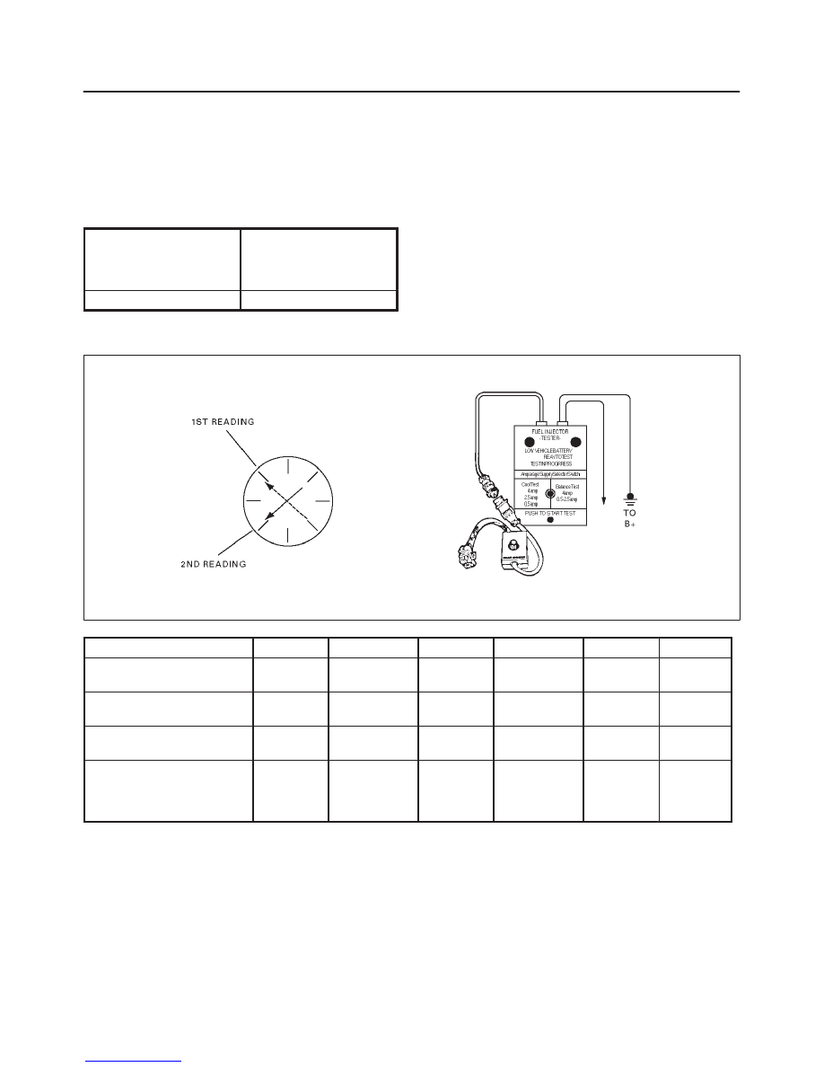
7.The Fuel Injector Balance Test portion of this chart
(Step 7 through Step 11) checks the mechanical
(fuel delivery) portion of the fuel injector. An engine
cool-down period of 10 minutes is necessary in
order to avoid irregular fuel pressure readings due
to “Hot Soak” fuel boiling.
Injector Coil Test Procedure (Steps 1-6) and Injector Balance Test Procedure (Steps 7-11)
R262001
CYLINDER
1
2
3
4
5
6
1st Reading (1)
296 kPa
(43 psi)
296 kPa
(43 psi)
296 kPa
(43 psi)
296 kPa
(43 psi)
296 kPa
(43 psi)
296 kPa
(43 psi)
2nd Reading (2)
131 kPa
(19 psi)
117 kPa
(17 psi)
124 kPa
(18 psi)
145 kPa
(21 psi)
131 kPa
(19 psi)
130 kPa
(19 psi)
Amount of Drop
(1st Reading–2nd Reading)
165 kPa
(24 psi)
179 kPa
(26 psi)
172 kPa
(25 psi)
151 kPa
(22 psi)
165 kPa
(24 psi)
166 kPa
(24 psi)
Av.drop = 166 kPa/24 psi
±
10 kPa/1.5 psi
= 156- 176 kPa or 22.5-
25.5 psi
OK
Faulty, Rich
(Too Much
Fuel Drop)
OK
Faulty, Lean
( Too Little
Fuel Drop)
OK
OK
NOTE: These figures are examples only.

6E2–65
RODEO 6VD1 3.2L ENGINE DRIVEABILITY AND EMISSIONS
Injector Coil Test Procedure (Steps 1-6) and Injector Balance Test Procedure
(Steps 7-11)
Step
Action
Value(s)
Yes
No
1
Was the “On-Board Diagnostic (OBD) System Check”
performed?
—
Go to Step 2
Go to
OBD
System
Check
2
1. Turn the engine “OFF.”
NOTE: In order to prevent flooding of a single cylinder
and possible engine damage, relieve the fuel pressure
before performing the fuel injector coil test procedure.
2. Relieve the fuel pressure. Refer to
Test Description
Number 2.
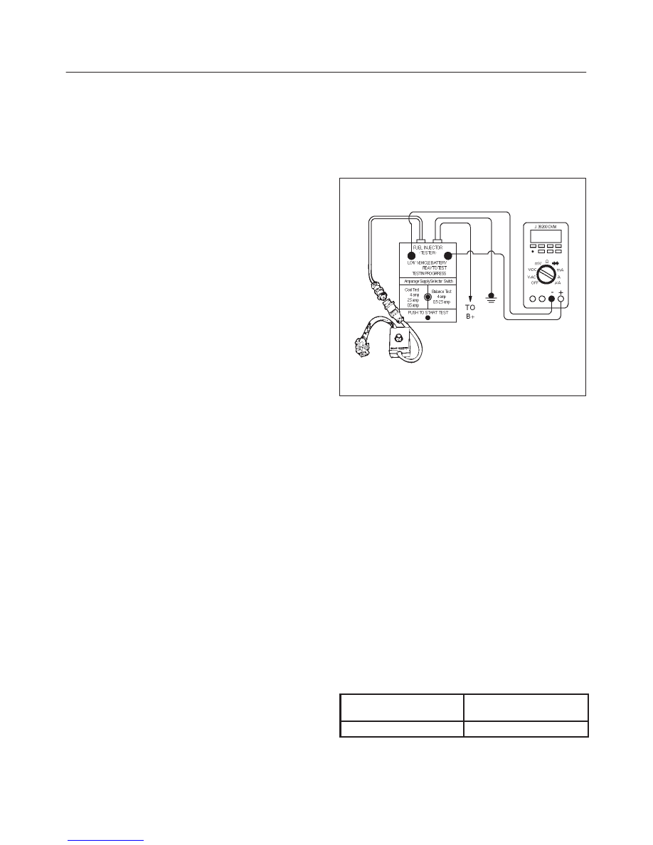
3. Connect the J 39021-5V Fuel Injector Tester to B+
and ground, and to the J 39021-90 Injector Switch
Box.
4. Connect the injector switch box to the grey fuel
injector harness connector located at the rear of the
air cleaner assembly.
5. Set the amperage supply selector switch on the fuel
injector tester to the “Coil Test” 0.5 amp position.
6. Connect the leads from the J 39200 Digital
Voltmeter (DVM) to the injector tester. Refer to the
illustrations associated with the test description.
7. Set the DVM to the tenths scale (0.0).
8. Observe the engine coolant temperature.
Is the engine coolant temperature within the specified
values?
10
°
C (50
°
F)
to 35
°
C
(95
°
F)
Go to
Step 3
Go to
Step 5
3
1. Set injector switch box injector #1.
2. Press the “Push to Start Test” button on the fuel
injector tester.
3. Observe the voltage reading on the DVM.
IMPORTANT: The voltage reading may rise during the
test.
4. Record the lowest voltage observed after the first
second of the test.
5. Set the injector switch box to the next injector and
repeat steps 2, 3, and 4.
Did any fuel injector have an erratic voltage reading
(large fluctuations in voltage that did not stabilize) or a
voltage reading outside of the specified values?
5.7-6.6 V
Go to
Step 4
Go to
Step 7
4
Replace the faulty fuel injector(s). Refer to
Fuel
Injector.
Is the action complete?
—
Go to
Step 7
—

6E2–66
RODEO 6VD1 3.2L ENGINE DRIVEABILITY AND EMISSIONS
Injector Coil Test Procedure (Steps 1-6) and Injector Balance Test Procedure
(Steps 7-11)
(Cont'd)
Step
No
Yes
Value(s)
Action
5
1. Set injector switch box injector #1.
2. Press the “Push to Start Test” button on the fuel
injector tester.
3. Observe the voltage reading on the DVM.
IMPORTANT: The voltage reading may rise during the
test.
4. Record the lowest voltage observed after the first
second of the test.
5. Set the injector switch box to the next injector and
repeat steps 2, 3, and 4.
Did any fuel injector have an erratic voltage reading
(large fluctuations in voltage that did not stabilize) or a
voltage reading above the specified value?
9.5 V
Go to
Step 4
Go to
Step 6
6
1. Identify the highest voltage reading recorded (other
than those above 9.5 V).
2. Subtract the voltage reading of each injector from
the highest voltage selected in step 1. Repeat until
you have a subtracted value for each injector.
For any injector, is the subtracted Value in step 2
greater than the specified value?
0.6 V
Go to
Step 4
Go to
Step 7
7
CAUTION: In order to reduce the risk of fire and
personal injury, wrap a shop towel around the
fuel pressure connection. The towel will absorb
any fuel leakage that occurs during the
connection of the fuel pressure gauge. Place the
towel in an approved container when the
connection of the fuel pressure gauge is
complete.
1. Connect the J 34730-1 Fuel Pressure Gauge to the
fuel pressure test port.
2. Energize the fuel pump using the Tech 2.
3. Place the bleed hose of the fuel pressure gauge into
an approved gasoline container.
4. Bleed the air out of the fuel pressure gauge.
5. With the fuel pump running, observe the reading on
the fuel pressure gauge.
Is the fuel pressure within the specified values?
296 kPa-376
kPa (43-55
psi)
Go to
Step 8
Go to
Fuel
System
Diagnosis
8
Turn the fuel pump “OFF.”
Does the fuel pressure remain constant?
—
Go to
Step 9
Go to
Fuel
System
Diagnosis
Нет комментариевНе стесняйтесь поделиться с нами вашим ценным мнением.
Текст